WHAT IS GEARBLOCS?
The short answer is, GEARBLOCS is a STEM (Science, Technology, Engineering, and Math) building system for adults and children that is adapted to having the pieces 3D printed. It's an option that allows the user to combine 3d printing with building, and take it to a whole other level by integrating ball bearings, gears, motors, and servos to build full RC controlled devices. The beauty of a 3D printed STEM system is control of the quantity of each piece. If you lose a piece, just print another one. Also many of the pieces are small and can be printed overnight, or during times when your printer would otherwise be idle, using small amounts of material like spools with only a small amount of filament left. Before building the GEARBLOCS system, we recommend you review our article about precision 3D printing: FUNCTIONAL PRECISION 3D PRINTING – COMMERCIAL 3D FILES
WHY NOT LEGOS?
The most obvious question is, what's wrong with just using Legos? After all they are widely distributed. And answer to that is multifaceted. The first reason is that Legos were not designed around the 3D printing world. As anyone knows that has designed and printed many models, 3D printing has certain design requirements. Overhangs must be addressed because of limitations with additive manufacturing. 3d printing is not as precise as plastic injection molding, so tolerance issues but be considered when building any assembly with 3D printing. And 3D printing as not as good at very small details, so objects need to be designed considering the limitations on size.
PINS VS. PROTRUSIONS
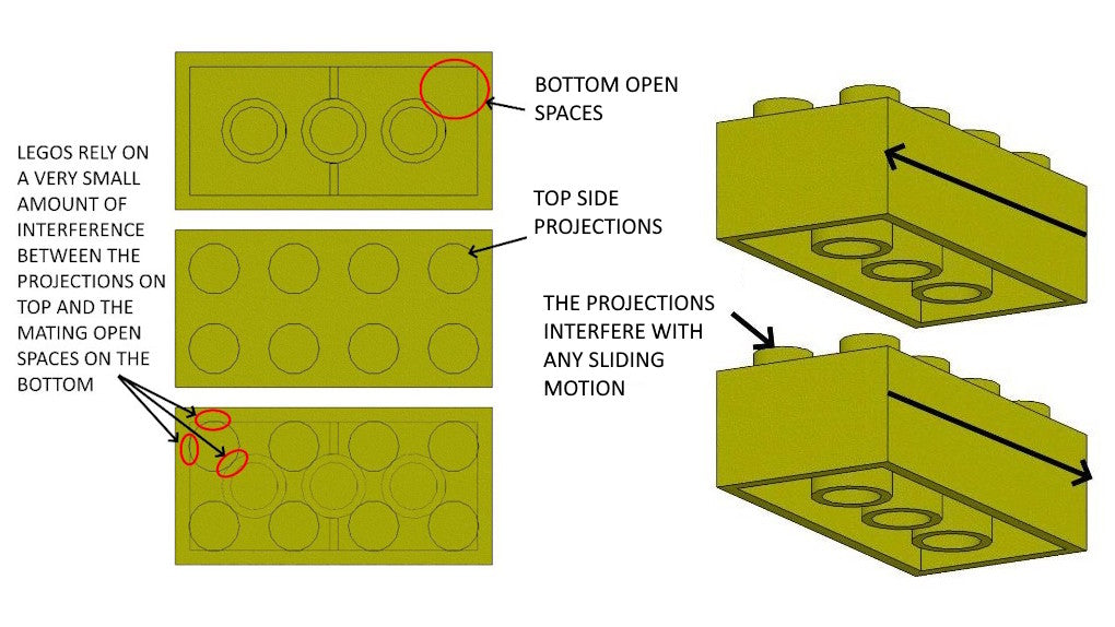
Legos are designed with fixed projections on the top side that must mate with open spaces on the bottom size, with a very precise amount of interference. If the interference is off by the most microscopic amount, the fit between pieces will be too tight or too loose. This doesn't lend itself well to 3D printing. Another reason to move away from fixed projections is that they inhibit any sliding motion between the beam parts. So for example if you wanted to build a crane with an arm that can extend or retract, with Legos you have the problem of the projections on top hanging up on the open spaces on the bottom. Whereas with GEARBLOCS, the beam surfaces are smooth and can slide easily against one another.
GEARBLOC PINS & BEAMS
Rather than using fixed projections on the beams, the GEARBLOCS system uses connector pins that can lock beams together in either vertical or horizontal orientation. This design eliminates the need for super tight size tolerances, because the pins are split design, and have a spring action. This allows for more variation in the final size of the pins and the beam holes. Additionally, the absence of fixed projections keeps the outer surfaces of the beams smooth, allowing for assemblies utilizing a running/sliding feature design, such as the extension arm of a crane. The image below shows cut away views of a GEARBLOCS beam with pins installed so you can see how they work. This type of connecting system also more closely mimics real work assemblies that use fasteners of various kinds for connecting parts.
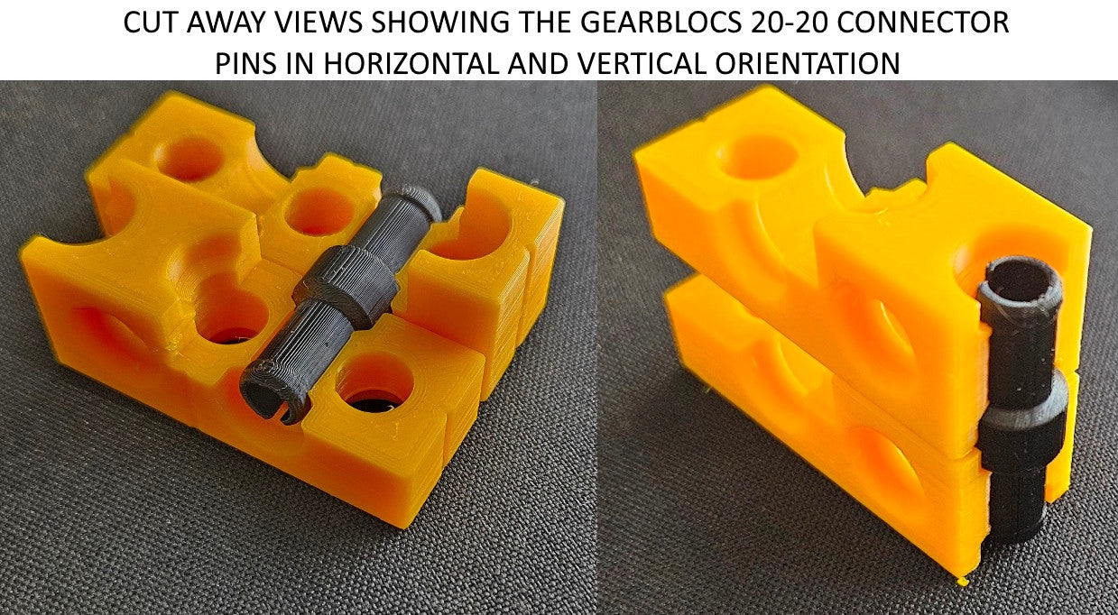
image showing beams cut away so you can see how pins work inside the holes
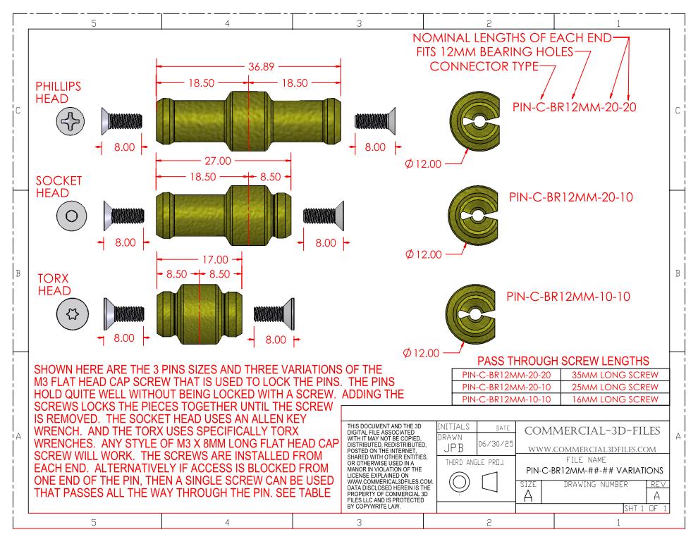
The image below shows the 3 sizes of connector pins used in the GEARBLOCS system, with an explanation of the part number and what the various numbers and letters mean in the part number. All 3 pins work the same way, only the lengths of each end of the pin are different. Pins hold well for building assemblies without the additional screws. But if you going to apply RC controlled motors to your devices built using GEARBLOCS, you can add the locking screws, which expands the pin makes the pin nearly impossible to remove until the screw is removed first.
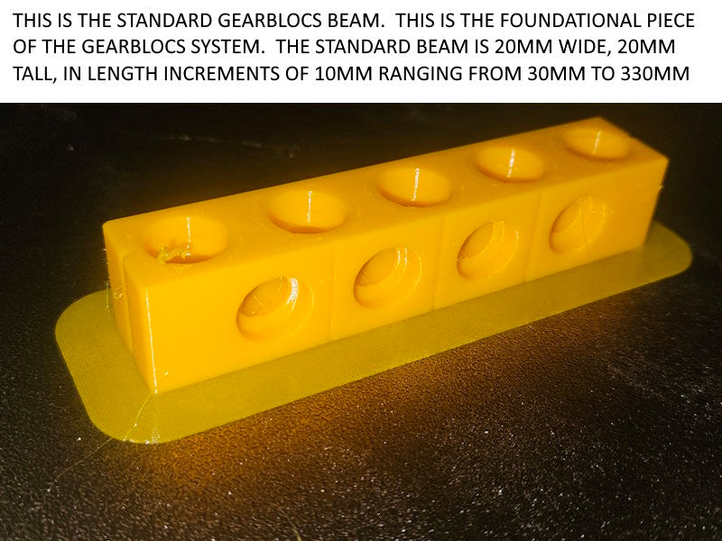
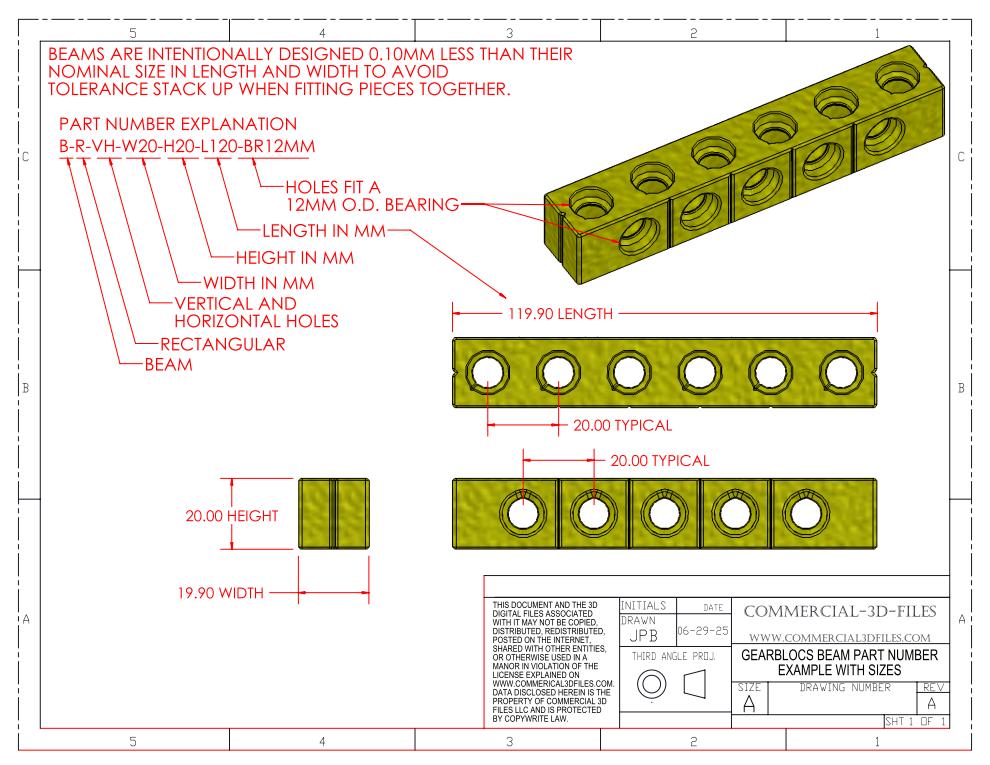
The standard GEARBLOC beam is 20mm tall and 20mm wide, with lengths available in 10mm increments. The image below shows an example drawing of the standard GEARBLOC beam with an explanation of the part number and what the various numbers and letters mean in the part number. GEARBLOC beams also come in 10mm heights, and the GEARBLOC plates are 10mm high with a smooth side and a side that has connector holes.
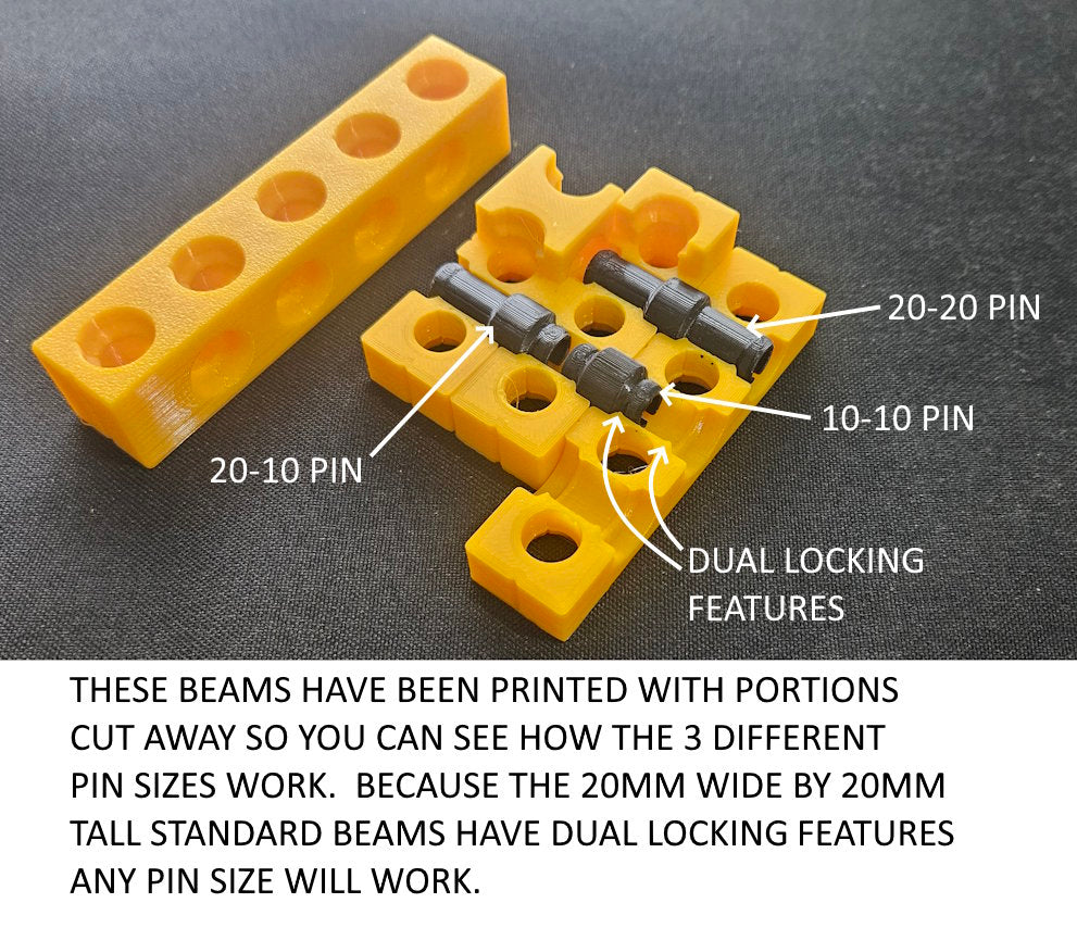
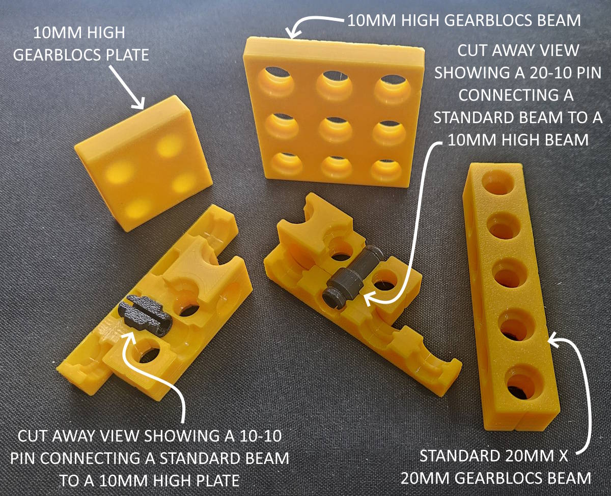
In the image below, parts of the standard beam have been cut away so you can see how the pins work inside the holes. Because the standard size beam has dual locking features in every hole, any size pin can be used to connect these. Using a pin with a 10mm end causes the pin to only pass half way through the 20mm beam, which allows you to have another 10mm pin in the same hole on the other side. This increases the options for how to build your assemblies. See below for an example.
In the image below you can see various connections between standard beams, 10mm high beams, and plates. A pin with a 10mm end must be used to connect a 10mm high plate or 10mm high beam to anything else.
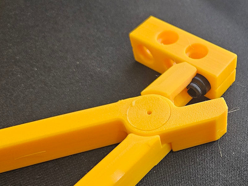
The pins can be a little difficult to remove with just your fingers, especially the 10mm length ends of a pin. So we have designed a 3d printable pin pliers for help with inserting and removing pins. The files for the pin plyers are provided with the purchase of the pin files.
The entire GEARBLOC system is built around the GEARBLOCS beam, which is a 20mm x 20mm x variable length plastic beam that can accept a 12mm O.D. bearings and which can be connected both vertically and horizontally to other beams, as well as plates and various other types of parts. GEARBLOCS beams are designed for maximum flexibility in building. The system also comes with gears, shafts, sprockets, chains, wheels, etc and various other 3D printable parts to allow for building functional machines and RC powered land toys.
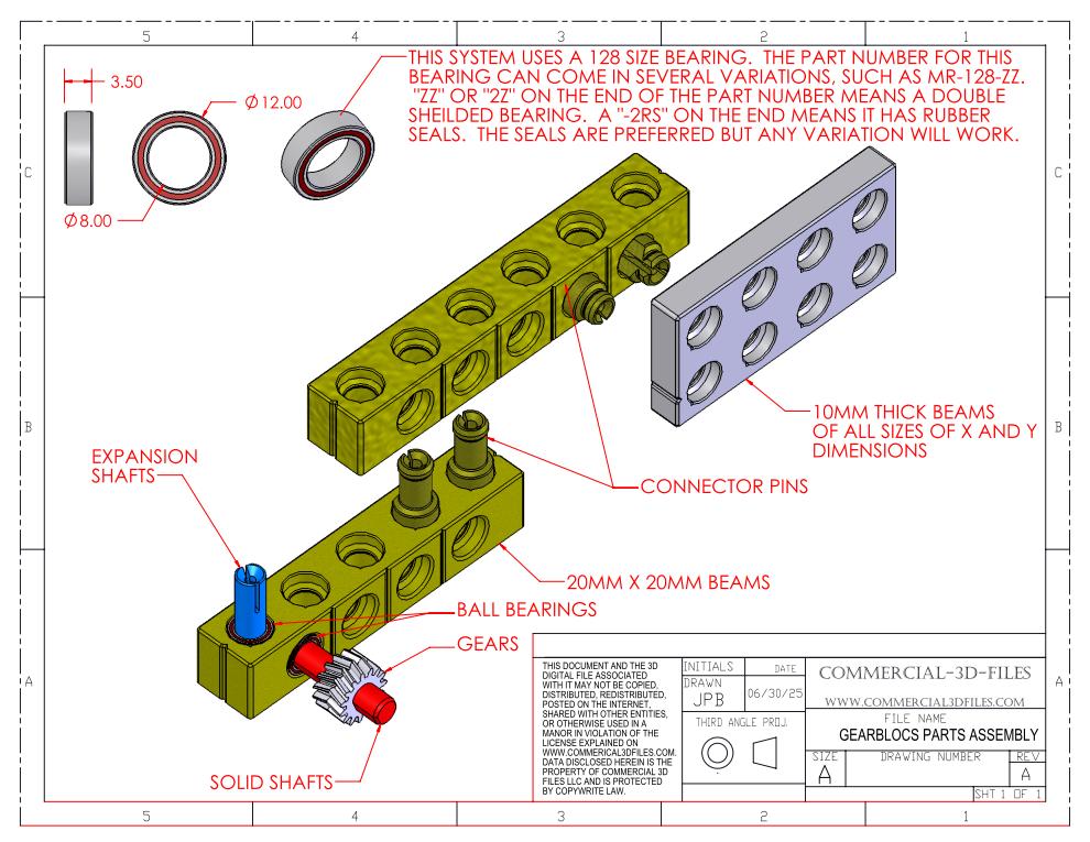
EXAMPLE OF HOW GEARBLOCS BEAMS ASSEMBLE WITH OTHER PARTS
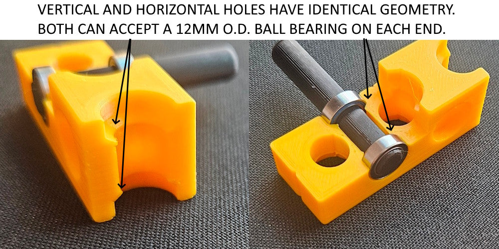
Both the horizontal and vertical holes in GEARBLOC beams have identical geometry. Either can accept a 12mm O.D. x 8mm I.D. ball bearing in either end of the hole, allowing for higher speed operation of RC designs with shafts, gears, sprockets, and wheels, etc.
In developing the design for the GEARBLOCS system, we experimented with horizontal holes that were peaked in design to avoid printing with supports, and also round holes using 3D printed supports. In the end, we found that the round horizontal holes printed with supports were not smooth enough where the supports touch, and as such they didn't provide better holding contact with the pins. Being able to print without supports was ultimately the way to go. Additionally the beams are designed with seam locations designed in so the seams won't interfere with the function of the pins. Beams are modeled 0.10mm smaller in outer length and width (but not pin hole spacing) so as to avoid a tolerance stack up when assembled that might lead to assembly problems due to interference.
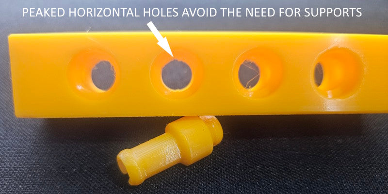
THE IMAGE ABOVE SHOWS HOW WE AVOID SUPPORTS WHEN PRINTING GEARBLOCS
The GEARBLOCS system pins also have a built in locking feature that utilizes an M3 flat head cap screw to lock the pin in place. These are suitable for connecting beams and plates when they absolutely must not come apart. The pins alone hold pretty well, but when the M3 screw is inserted inside the pin, it will not allow the beams to come apart. M3 screws can be inserted from both ends of the pin to pass part way through, or one screw can be insert from only one end and pass all the way through. This allows for great flexibility in how you build your assemblies.
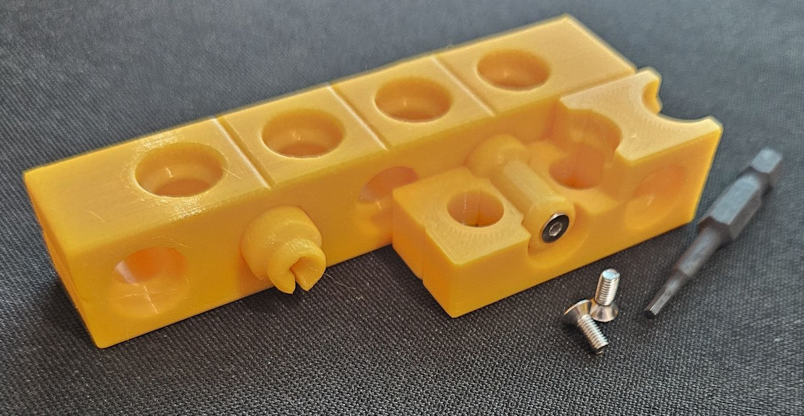
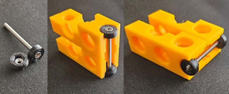
The GEARBLOCS system has a provision for locking beams together with metal fasteners. A washer can be 3d printed that accepts an M3 flat head cap screw, and another washer that accepts an M3 hex nut which can be normal hex or a nylok hex nut. The image below shows an example of how this works with a 40mm long screw. By using even longer screws like 60mm and 80mm you can lock 3 and 4 beams together for a very secure hold in assemblies that will be subjected to substantial forces.
GEARBLOC SHAFTS
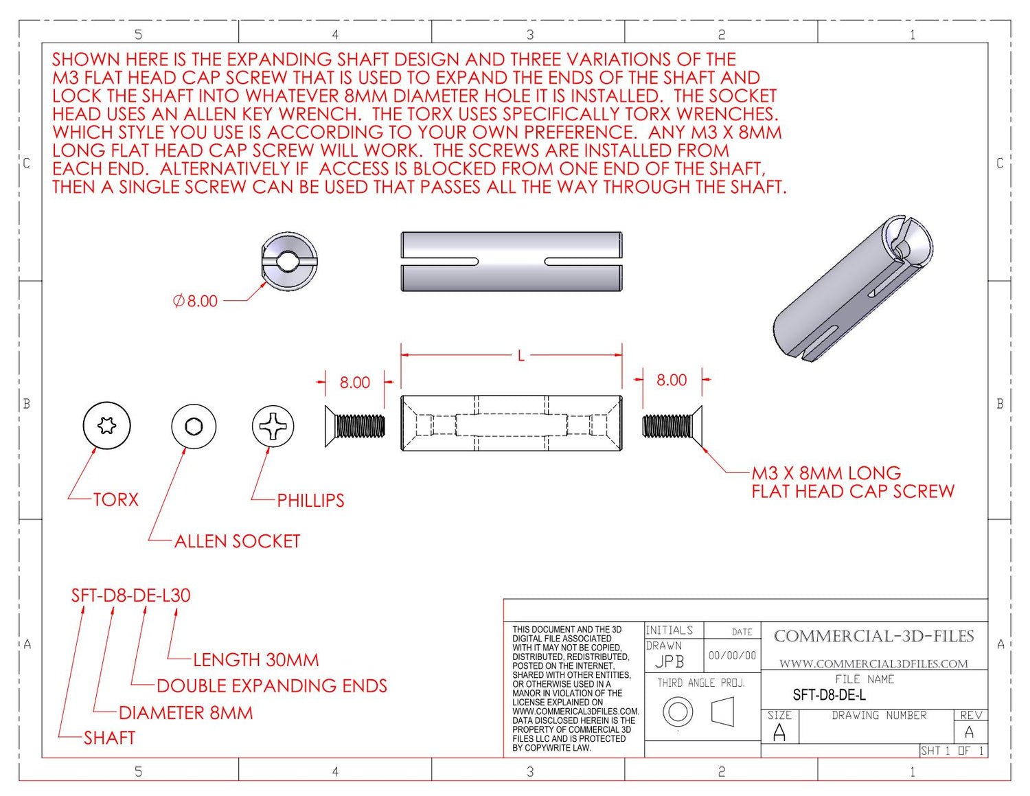
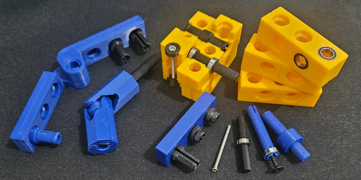
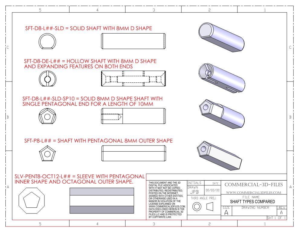
The GEARBLOCS system includes shafts that can be used in assemblies for making functional devices. The most common shaft used is D shaped, meaning it has a flat on one side. This serves dual purposes, both acting as a locking feature when used with sprockets and gears, and also allowing for 3D printing horizontally without supports. It's important for shafts to be printed horizontally for strength. D shaped shafts come in 8mm O.D. for use with matching ball bearings. Shafts also come as solid, that rely on a friction fit in bearings. Also picture below is a variation of the D shaped shaft called a split expansion shaft that is designed to accept an M3 x 8mm long flat head cap screw. The screws in an expansion shaft cause the end of the shaft to expand and lock into the bearing or other feature that the end is installed in, and also the screws add substantial strength to the shafts. Information about these screws and sources for them are provided with the purchase of expansion shaft STL files. Shafts come in a vast array of lengths. The third type of shaft is a pentagonal shaped shaft. This shaft is used where the shaft must fit inside a socket, on a part that must be printed horizontally for strength. A D shaped horizontal hole doesn't print well because of the need for supports. But a pentagonal shape, having 5 sides, has a peaked top, and can be printed horizontally without supports. Shafts also come in combinations of shapes, such as a D shape on one end a pentagonal shape on the other, for use in specific applications. The image below shows examples of these various types of shafts used in the GEARBLOCS STEM building system.
The image below shows an example of an expansion shaft and an explanation of the part number and what each of letter and numbers mean in the part number.