Purpose
The purpose of this page is to offer an explanation of various factors that affect the surface quality, strength, and precision of 3d prints parts. Many of the files available for print on commercial3dfiles.com such as RC Toys and Gearblocs STEM Building System components require a higher level of precision due to components that must fit and function together. We hope the information offered here will help you go from printing objects for visual display to printing functional devices with intermeshing parts that fit and function as intended.
Tools of Precision
Before you can manufacture anything with precision, you must have ways to precisely measure what you make. Figure 1 below is a selection of tools we recommend for printing parts that need to fit together and function in a specific way.
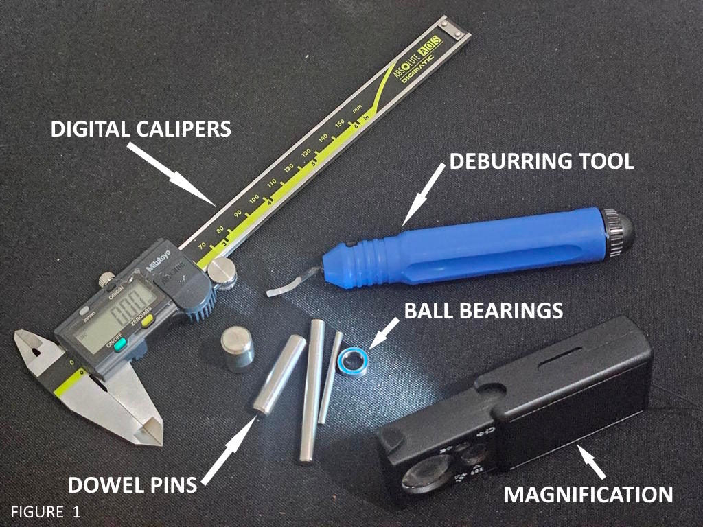
A selection of tools used for precision 3d printing
Digital Calipers
A digital caliper is a must have for precision 3d printing. There are many brands available that run from complete junk at the cheap end to a fine precision tool at the more expensive end. This is one area we recommend not going cheap. A cheap caliper will be inaccurate and inconsistent. Our favorite brands that we have first hand experience with are Mitutoyo and Starrett. There are many cheap brands that are really bad quality, but one that we’ve seen used with some success is Fowler. We strongly advise you not buy one any cheaper than Fowler. Digital calipers should be kept clean. You must select the units you want to measure in, and then set them to zero before use. Clean the faces of the jaws by wiping with your clean finger or a tissue, then close the jaws completely, and press the zero. See figure 2 below.
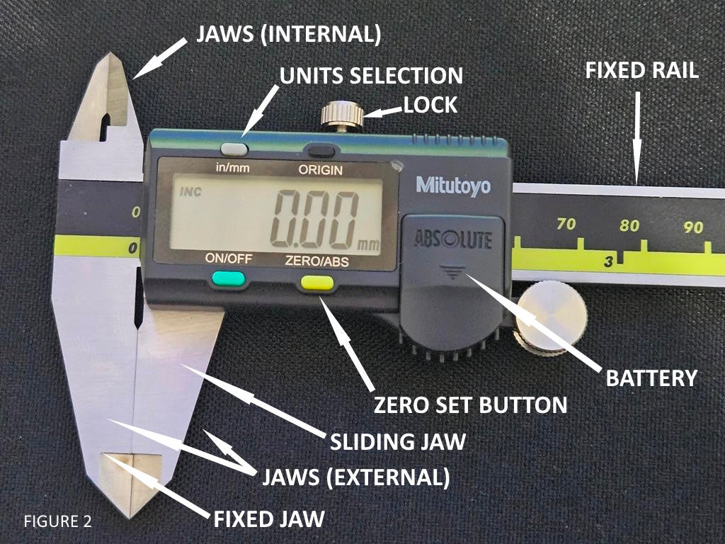
The primary parts of a digital caliper
One of the most often unknown or overlooked adjustments on calipers is the gibs. A gib is a wedge device inside the caliper that adjusts the tension of the sliding jaw of the caliper to the fixed rail of the caliper. If the gibs are too loose, the sliding jaw can rock a little (feel slightly loose) on the fixed rail and cause the jaws to not stay parallel. If the gib is too tight, the sliding jaw won't slide anymore. Adjust the screws to the most tension you can for the jaw to still be able to slide smoothly on the fixed rail. You will find this to be a very small amount of tightening tension on the gib adjustment screws.
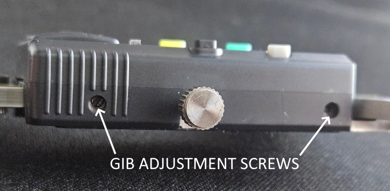
IMAGE SHOWING THE SCREWS FOR ADJUSTING THE GIBS ON CALIPERS
Digital Calipers can be used for measuring outside dimensions, inside dimensions, and also depth by utilizing the rod that protrudes from the center of the rail. Care must be taken not to use too much force in taking measurements. It’s possible to squeeze calipers hard enough to flex the steel and cause measurement errors. Use only enough force to make the jaws fully touch the surfaces to be measured. See figure 3 below.
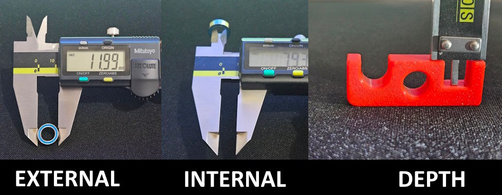
The three ways that digital calipers can be used to measure
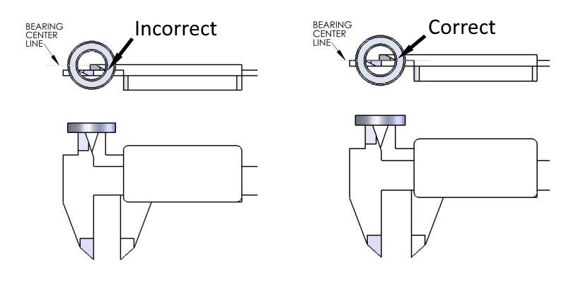
It's important to orient the parts such that the jaws of the calipers are square to the surfaces of the parts. Failure to do so will result in measurement errors.
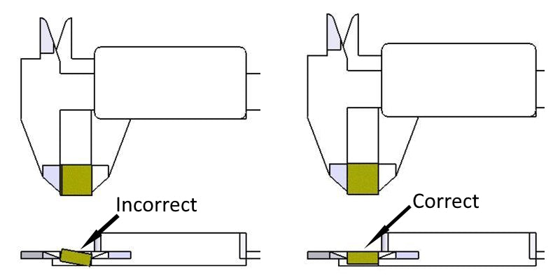
In the example below where the part isn't square with the jaws, the calipers would give a measurement larger than the true value.
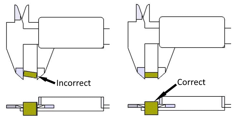
In the example below, failure to get the internal measurement jaws of the calipers on the centerline of the ring will result in a measurement smaller than the true value. Take time to wiggle the parts around and find the centerline by feel. The centerline of an internal curved ring, or a hole, will be where the calipers read the largest value. NOTE: Calipers are not as accurate at measuring a concave curve, or hole, as they are at measuring inside flat surfaces or measuring outside surfaces. This is due to the geometry to the calipers themselves.
Dowel Pins
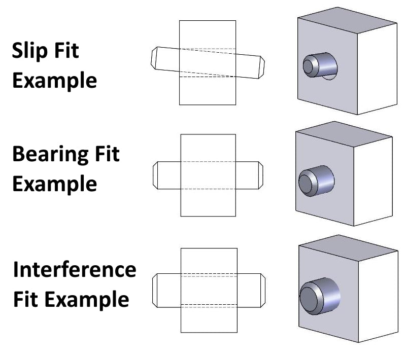
Steel dowel pins are a very precise tool for measuring holes to verify fit. When you buy a 6mm diameter steel dowel pin, for example, it will normally have a tolerance of +.002mm to +.009mm (that's +2 microns to +9 microns). You can use dowel pins to check the size of 3d printed holes with much more accuracy than using calipers. There are 3 categories of fit when talking about a round shaft (such as a dowel pin) fitting inside a round hole. If the dowel pin will pass through the hole without much force, then it is a "slip fit". When you insert a dowel pin inside a hole, try to move it around and see if you can feel any movement. If there is movement, that is reflective of the hole size being larger than the pin, a value that we call "clearance". As you reduce the size of the hole closer to the size of the pin, you reach a point where there is no more clearance, the pin can still be inserted into the hole with the force of just your fingers, but the pin fits snug and cannot be wiggled at all inside the hole. We call this a "bearing fit". A bearing fit is right on the line between a slip fit and a press fit. It means the hole is very close to the dowel pin size, normally within a few microns of the pin size. There is a point where the pin is slightly larger than the hole, and it requries more force to push the pin into the hole. The amount of force is relative to exactly how much bigger the pin is than the hole. We call this a "press fit" because in metal working, it requires an actual press (mechanical or hydrualic) to force the pin into the hole. A press fit is also known as an "interference fit". It means that material is having to compress, or move, in order to allow the pin to pass through the hole.
Ball Bearings
Ball Bearings are a mechanical component that has a very precision outer diameter ( O.D. ) and also a very precision inner diameter ( I.D. ) This makes them equally suitable for checking holes much in the same way dowel pins are used, and also for checking 3d printed pins or other round protrusions by adjusting the feature's size until it fits to the inner diameter ( ID ) of the ball bearing. Here, the same principles of fit apply as with the dowel pin described above.
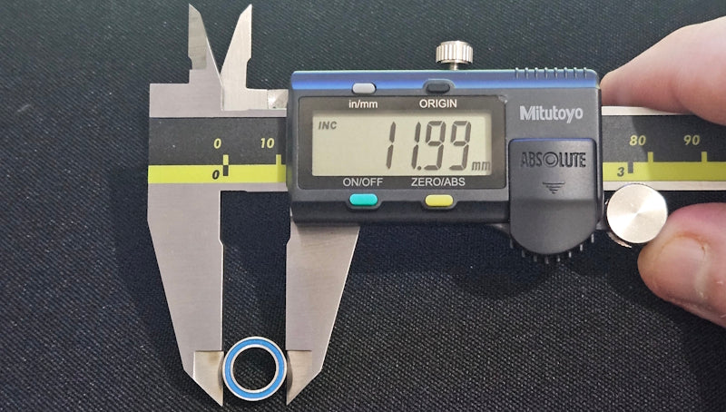
Image of precision calipers measuring a 12mm diameter bearing
The image below shows an example of using both a dowel pin for checking the size of a hole, and a ball bearing for checking the size of a pin or shaft. In both cases the 3d printed objects require a light force for the dowel pin to be inserted in the hole or the pin to be inserted into the ball bearing, indicating a very precision fit.
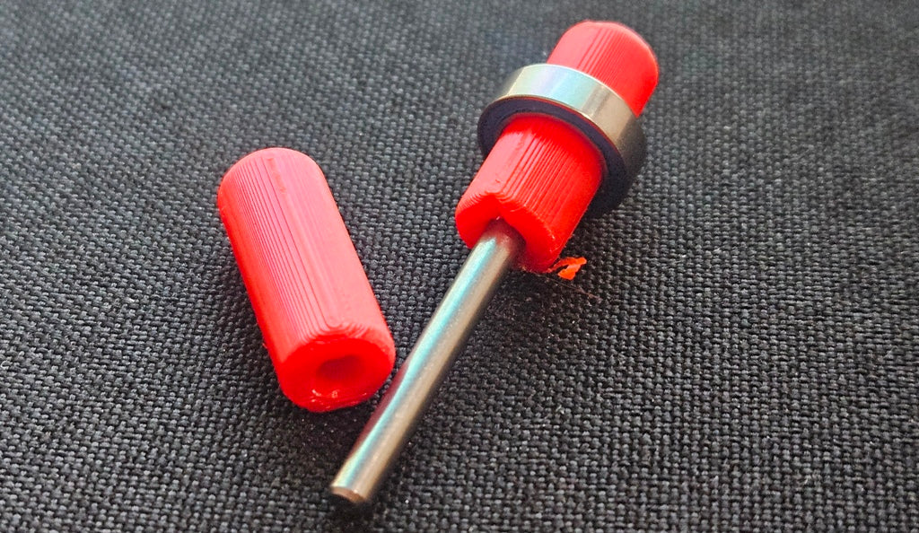
image showing the use of dowel pins and bearings to size 3d printed features
Tool Calibration
There is a big difference between static tools like dowel pins, bearings, etc, and dynamic tools like calipers or micrometers. A static tool is a fixed metallic object that doesn't change size or shape unless subjected to great force. A dynamic tool has moving parts, and in the case of digital calipers, it has electronic parts that can be damaged or malfunction. Something that is often unknown to new or casual users of calipers is that they need to be calibrated, or checked against a gage, a gage being a static object of precise and known dimensions. There are gages that are built to be gages, such as in the image below, that are specifically for calibrating and verifying tools. Then there are other objects that can be used as gages, such as precision steel dowel pins and ball bearings mentioned above. You can use these precision object to verify if your calipers are measuring correctly. It is wise to keep a few gages around for various common sizes that you must print with precision, and use these gages to check your calipers for accuracy frequently. I once had the tip of my caliper jaw become damaged very slightly from getting dropped. It bent the tip an amount too small to be seen, but enough to prevent the jaws from closing all the way due to the microscopic beak shaped bend right at the tip. I discovered this problem because the calipers were reading a value that was off by 0.1mm of known gages when I would check the gage at a spot on the jaws OTHER than where that tiny beak shaped bend was. After some investigate I could feel the tiny bend right at the end when I would slide my finger along the caliper jaw. I removed this defect very carefully using a fine precision stone. This issue caused a string of measurement errors that cost me a week of work due to measurement errors that were too great for the parts I was building.
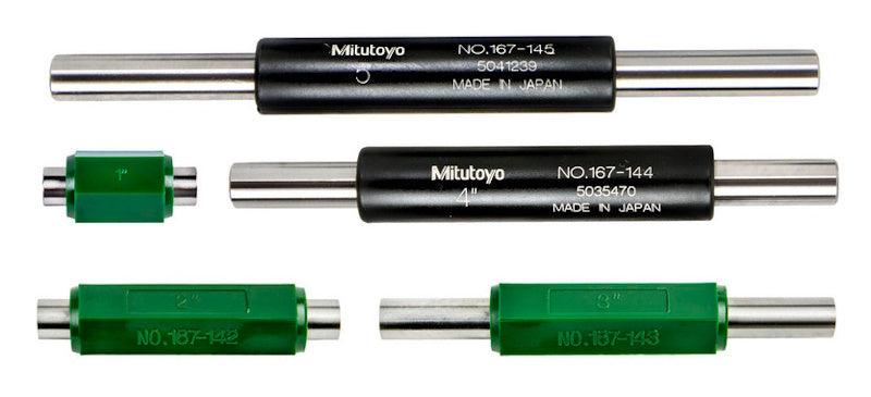
image of precision length gages for tool calibration
In the image below, a precision ball bearing is used to verify the accuracy of digital calipers. The bearing is a 12mm OD and 8mm ID. You can see the caliper is within 0.01 mm of the true size of the OD of the bearing. This is sufficient for calipers, as they are not capable of more precise measurements. The ID measurement is off by 0.05mm, but this is partly because calipers are less accurate at measuring internal round diameters. This phenomenon is due to the shape of the internal measuring jaws of the calipers and the way they must slide past each other. Using this information from the image, you would know therefore that your calipers will show a value that is 0.05mm smaller than the true value when measuring an 8mm inner diameter ( ID ). This amount of error changes with different diameters as the radius of the diameter changes. This is one reason I mostly use precision dowel pins, gage pins, or bearings to function as static gages, to check the fit of 3d printed holes, rather than calipers. I only use the calipers on small holes when an approximate value sufficient. The accuracy of the caliper in measuring internal holes will improve as the hole size gets larger. But it will never be as precise as using a gage. However, sometimes it just isn't practical to have a gage for every hole size, and it's expensive for large cylindrical gages like 50mm diameter. For these the calipers will have to due.
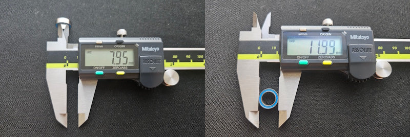
image of a ball bearing being used as a gage to calibrate digital calipers
Deburring Tool
A deburring tool is very helpful in smoothly removing the sharp edges around a part, or for removing a brim. See image below.
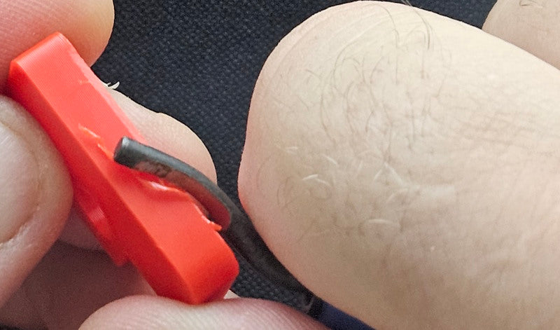
DEBURRING TOOL IN USE ON 3D PRINTED PART
Magnification
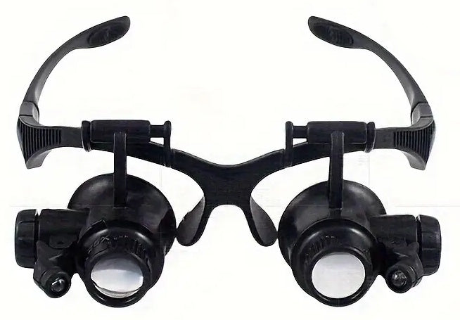
In the example below, using magnification would greatly enhance the ability to see fine details like over-extrusion in the case of this image vs. perfect wall layers, but it also assists with seeing blobs, layer separation, seams, or bulging corners that need to be corrected with linear advance settings. We recommend magnification with lights. The one pictured here isn't ideal because it's very small, but it works. A larger magnifying glass with lights built in is more convenient to use.
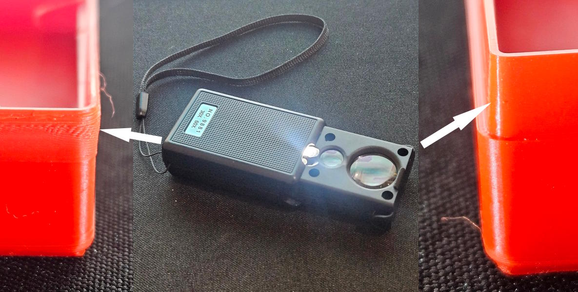
A hands free magnification device like the one pictured below would be much more user friendly.
Quality vs. Precision
Quality and precision are not exactly the same thing, but they do overlap. You can't achieve precision without first achieving quality. Quality refers more to the lack of defects in the surfaces of a 3d printed part. Precision refers to how close the size of the print is to the actual size of the 3d model, and how well interlocking parts fit together. Most of the parameters you would adjust to fix quality errors will also affect the true size of a 3d printed part. Examples of such parameters are extrusion ratio, line width, seam settings, linear advance, print speed, etc. It therefore does no good to attempt to achieve precision before achieving your desired level of surface quality. You should make all the necessary adjustments and test prints to fix extrusion errors and get your walls smooth, straight, and seams at their optimum BEFORE making the adjustments to dial in the precision of your 3d prints. Our intention with this section is not to provide a comprehensive troubleshooting guide for 3d printing errors. There are many very good guides already available online. Here we will only point out some various issues that need to be resolved prior to achieving high precision 3d printing.
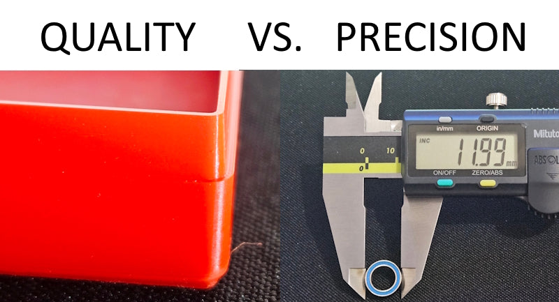
quality is smooth straight walls, precision is accurate sized parts
Extrusion Rate
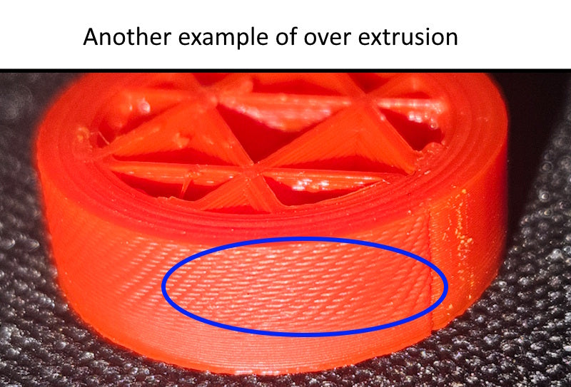
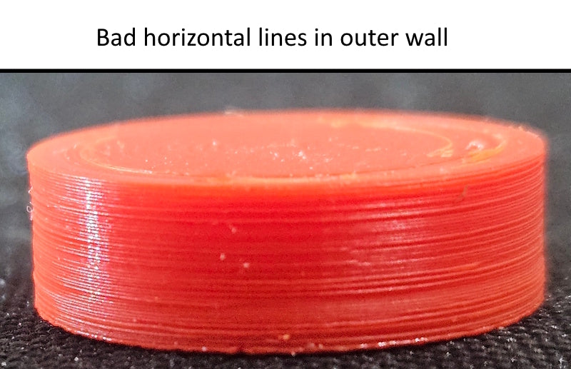
Extrusion rate is sometimes overlooked as a contributing factor to poor quality. But extrusion rate is the #1 thing to fix before trouble shooting any other aspect of quality. In the image below, the top two examples were printed with 1.3 extrusion ratio on the top left part and 0.7 extrusion ratio on the top right, just to show the outcome of extreme extrusion errors. In the bottom left, the extrusion error around the top of this part resulted from the fact that the 3d model of this wall tapering to be thinner at the top 1/4 of the wall. And this was printed with classic wall generator. As a result, it was trying to pack too much material into too thin of a wall at the top. Switching to Arachne wall generator made the next print of this part come out perfect. On the bottom right, these little random indentions in the wall are actually under extrusion. By switching from an extrusion ratio of 1.0 to 1.07, these defects stopped and the next print of this part was nearly perfect.
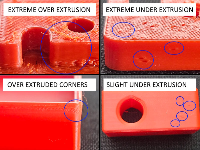
Examples of extrusion rate errors in 3d printing
Blobs and Bulges
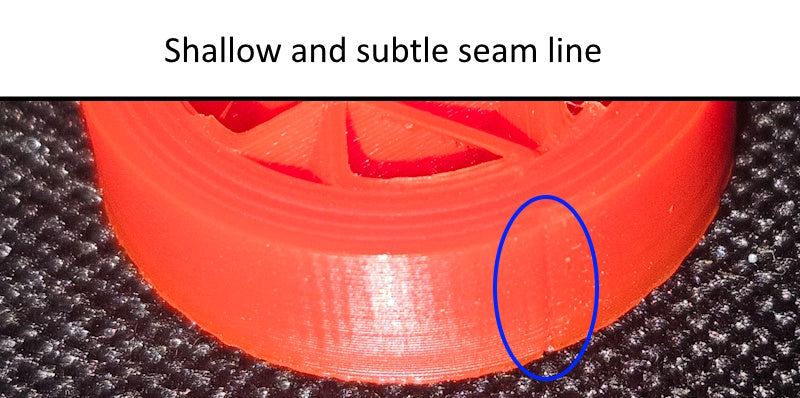
Blobs on the surface can occur anwhere, but they are common around the seam. We have grouped these with bulges because the cause and solution is largely the same. Or rather, the solution is largely the same if your extruder is functioning normally and not clogged or having worn gears,etc. These are both extrusion errors. In the examples below, this part started out with bad blobs and strings at the seam in figure 1. The solution was mostly switching from no linear advance to a linear advance setting of .06, and turning on a retraction of 3mm at 30mm/s speed. This corner where the seam was placed is a sharp internal corner. The nozzle must come to a complete stop at that corner in order to change directions as it travels around the perimeter of the part. Linear advance controls how the extruder motor slows down filament flow for corners and small radii to account for the deceleration, stop, and acceleration that must happen at sharp corners. Without this compensation, filament continues to flow too fast out of the nozzle as the nozzle comes to a stop at the corner, and thus we have the extra material deposited that we call "blobs". In figure 4, the issue is the same, even though it's an external corner. Linear advance slows the filament flow down in anticipation of the corner stop, so you don't get bulging external corners like this.
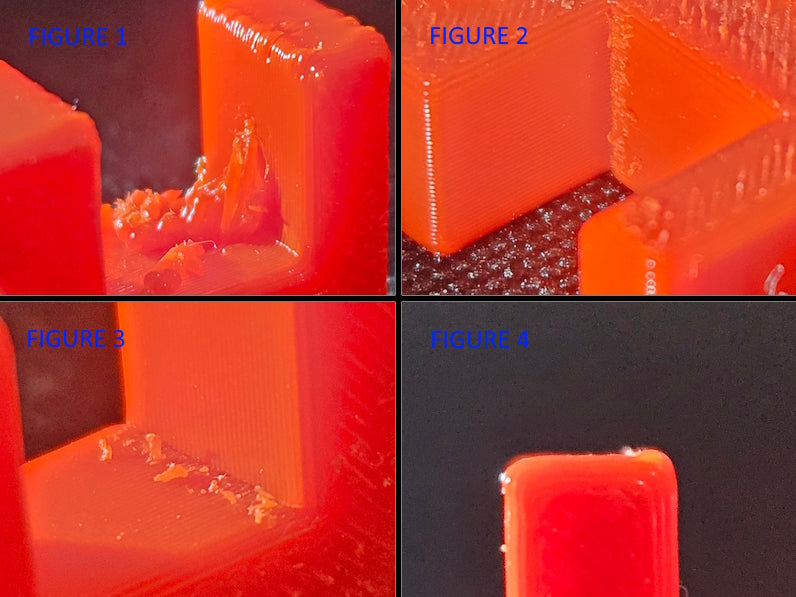
image showing variations of over extrusion and lack of linear advance control
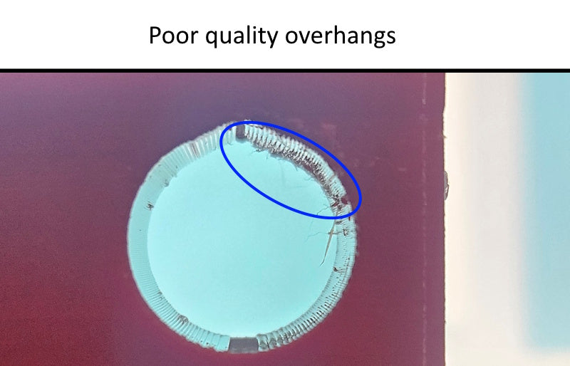
Other 3D Print Errors
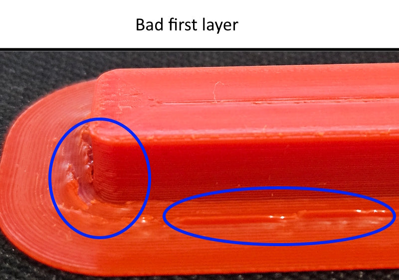
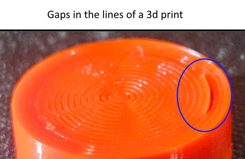
Below is a selection of other errors that can occur in 3d printing when the parameters aren't adjusted well. There are many others than what has been shown here. This section is not meant to be a comprehensive trouble shooting guide. There are plenty very good guides already on the web. This is intended to point out some various errors that must be resolved before you can print with a high degree of precision.
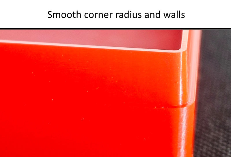
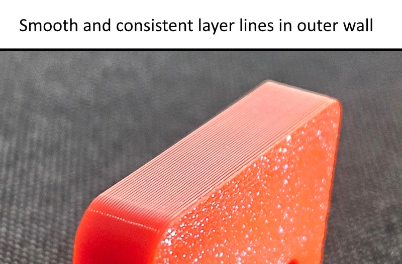
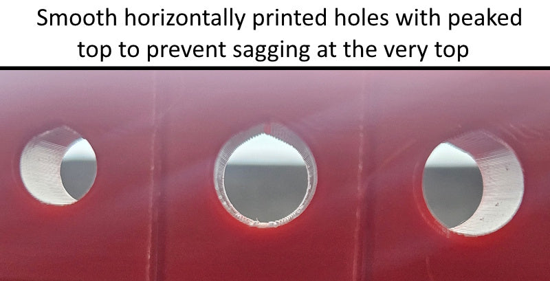
Quality 3D Prints
Below are some examples of the quality that is needed prior to doing high precision printing. Most decent quality printers are capable of achieving this level of quality. Often times it's necessary to slow down the print speed to achieve high quality and precision. This is especially true with filaments like PETG and ASA.
What is Precision
Once you have parameter settings developed in your slicer that are producing a high quality print with your chosen filament, it's time to dial in the precision of your prints. As previously stated, precision is defined as how closely your finished 3D print matches the actual size of the 3D model it was created from. Assuming you already have very good parameters developed that print your chosen material at high quality, there are two factors left that affect the final precision of your prints, and these are "shrinkage" and "contour compensation". These two factors affect the end result of your 3d prints in very different ways.
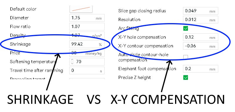
image of shrinkage and xy compensation slicer settings
3D Print Shrinkage
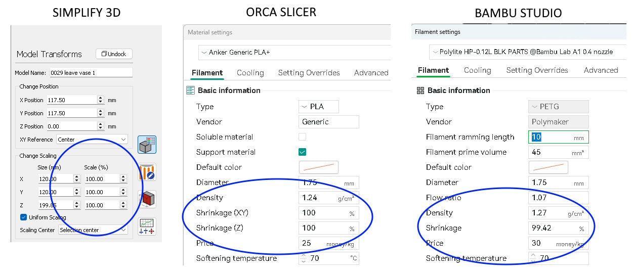
Almost all materials shrink as their temperature decreases. In 3D printing, the plastic is deposited in lines at high temperature such that the plastic is molten and will bond together. When a 3d print is finished it must cool back to room temperature. This cooling causes the part to change size. Fortunately, all slicers have a way to easily compensate for this change in size, although each slicer handles it a bit differently. Shrinkage is applied to a part as a percentage. Let's say for example that you use a material that has 1% shrinkage, or 99% retention, meaning it will shrink to 99% of the original printed size. If you start with a 3d model that is 100mm long and you print it, let it cool completely, and then measure it, the end result will measure to be 99mm long. However, let's say that same part is modeled at 10mm wide. The 10mm dimension will also shrink to a value that is 99% of its original modeled size, and thus will measure 9.9mm. So you see, shrinkage doesn't change all measurements an equal amount. Shinkage works on your parts as a percentage of the original 3d printed or 3d modeled size. Interestingly, 3d prints do not shrink as much in the Z axis, which probably has something to do with how the parts cool from bottom to top as the layers are being printed. Bambu slicer has an XY shrink factor setting, but doesn't have a shrinkage setting for the Z axis dimension. Orca looks like Bambu, but does have a Z axis shrinkage setting. Other slicers like Simplify 3D don't have a shrinkage parameter at all, and for those you can accomplish this by scaling the part in the XY and Z axis using the scale functions in the slicer. Be aware you may need to scale X and Y by a different amount than Z, or you may find it's not necessary to scale the z at all. Your own test prints and careful measuring will show you what is needed. Below is the formula for calculating the scale factor.
A=the 3d modeled dimension
B= the actual measured value of that dimension after cooling
Scale factor equals A / (B/100)
Measuring Shrinkage
Because shrinkage acts on a part as a percentage of each dimension, the amount is amplified as dimensions become larger. For this reason, when testing a new material and trying to determine shrink rate, it's best to print something at least 100m long for your testing. Let it also be understood here that each material has its own shrink rate. Switching brands or colors of a given material can yield a different shrink rate. It's best to test each material and keep careful notes, if precision matters.
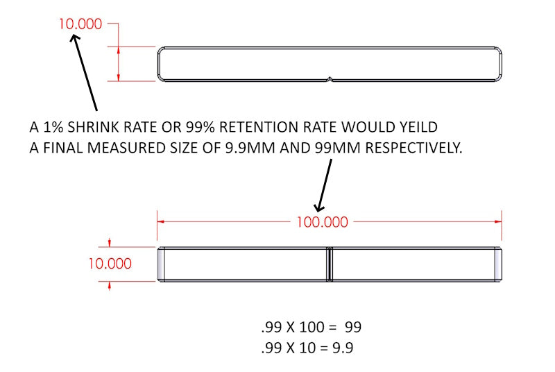
image illustrating how 3d filament shrinkage affects part size
XY Compensation
XY compensation is very different from shrinkage. The XY compensation parameter of a slicer is controlling the nozzle offset, as illustrated in the image below. In order to print a part the correct size, the slicer must put the centerline of the nozzle inside of the outer perimeter of the part. How much inside the perimeter is called the offset. The slicer makes a calculated guess at this value, and normally gets it pretty close. But many factors affect how filament flows from the nozzle, and thus how it spreads as the lines of filament are printed one by one. To give users more control of the size of their parts, a good slicer will have an XY compensation parameter to allow the user to adjust this offset and thus increase or decrease the size of the printed parts by a fixed amount. This is not applied as a percentage. This is a singular value that affect only the wall being printed and normally only the outer walls of a print.
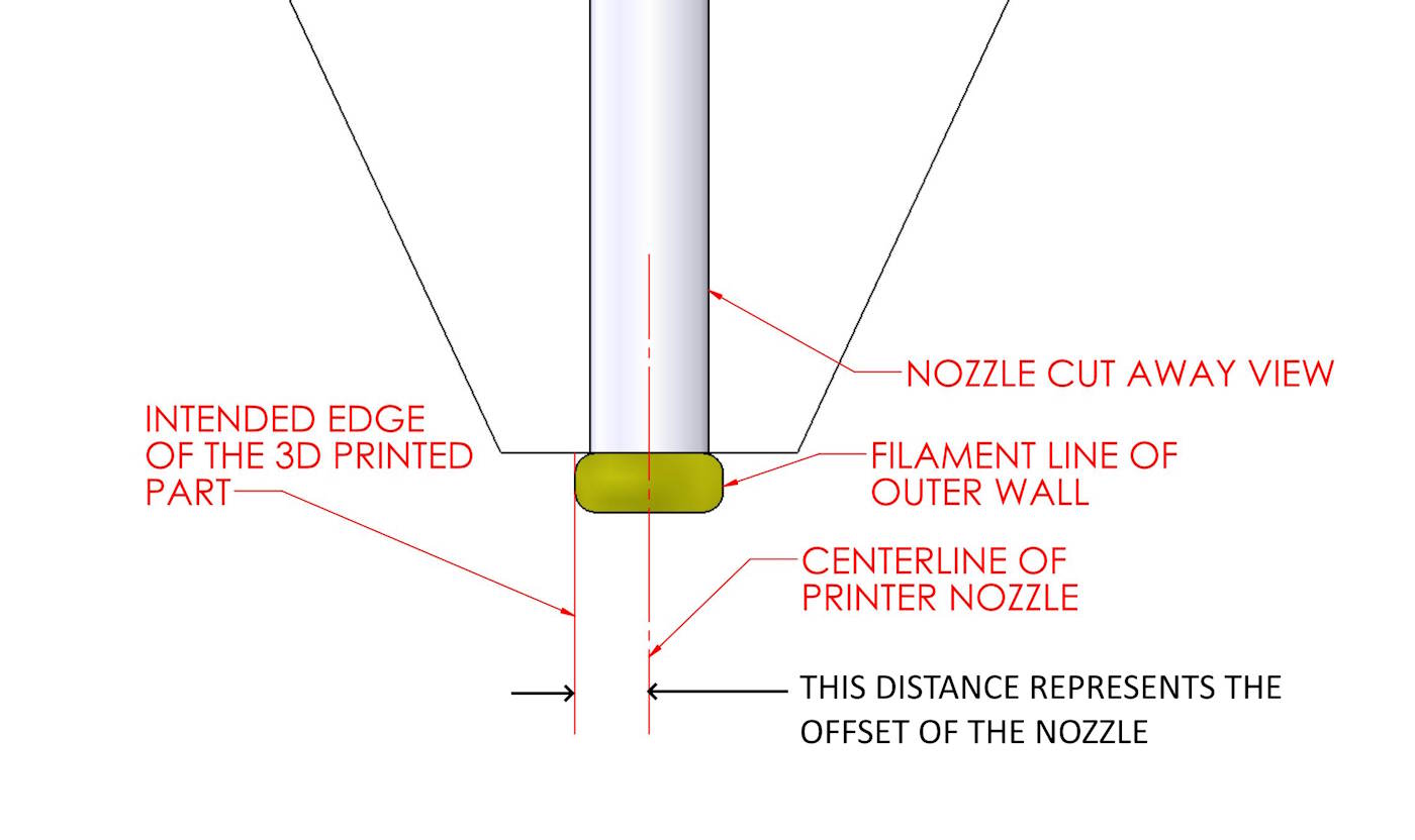
image illustrating nozzle offset in 3d printing
The image below illustrations this principle of XY compensation. If compensation is set to the correct value, the printer sets the offset of the nozzle perfectly so the edge of the outer filament lines are perfectly aligned with where the edge of the part should be. If the filament lines are printed too far inside of where the outer wall should be, the part will be undersized. The opposite is also true of course for oversized parts. We control this by adjusting the XY compensation with positive or negative values. Keep in mind, this applies all around the perimeters of the parts. So, if you change this value by 0.1mm, it will change the overall measurement of the part by 0.2mm, because it's printing on both sides of the part, so the offset change is affecting both sides, or rather all sides of the part. Fortunately, slicer programmers are smart enough to give us separate control of the outer perimeter from the inner perimeters (or holes) in the parts. This is good, because offset is a touchy setting and frequently doesn't have the same effect on outer perimeters as for holes.
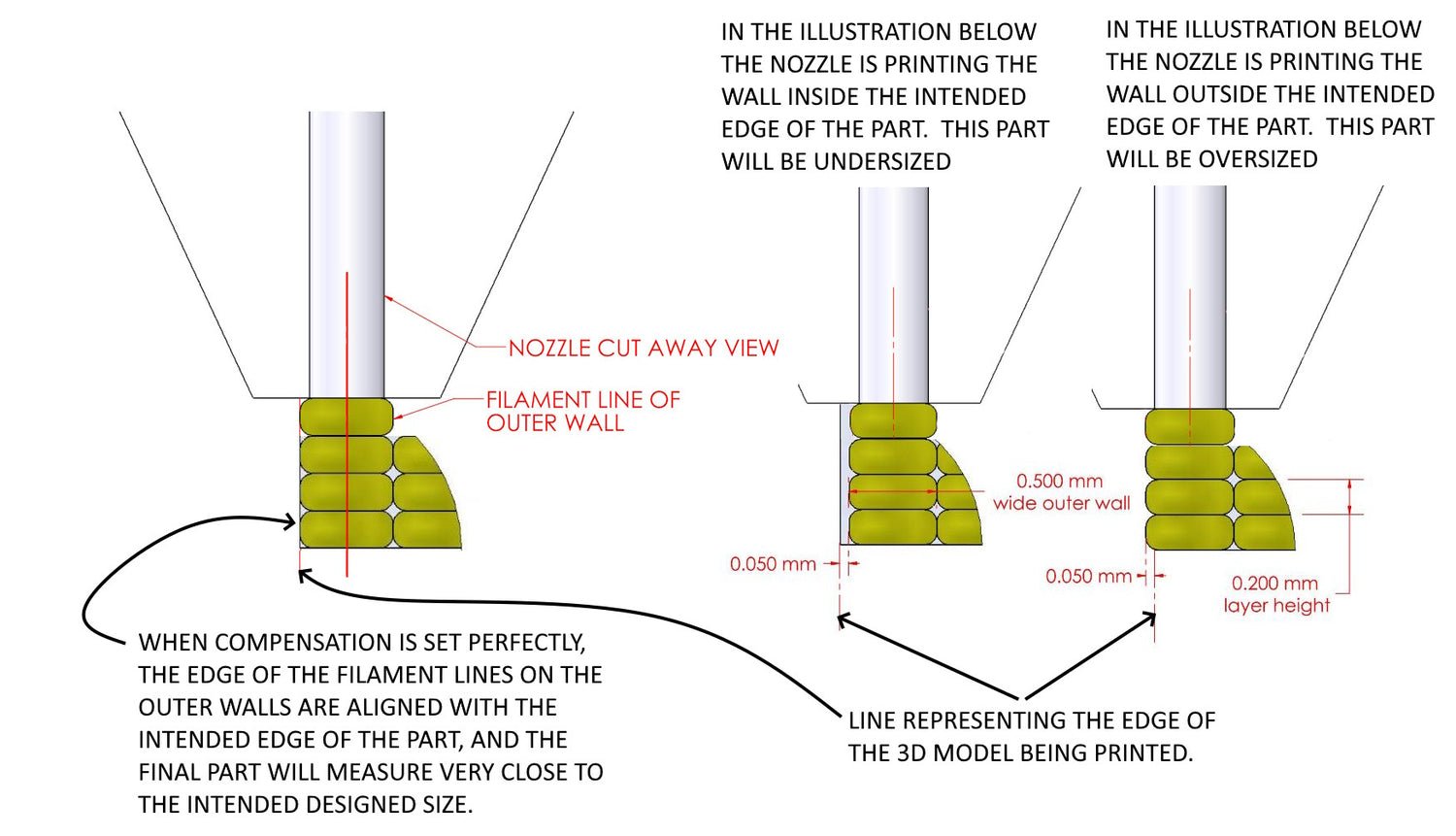
image showing how XY compensation affects part size
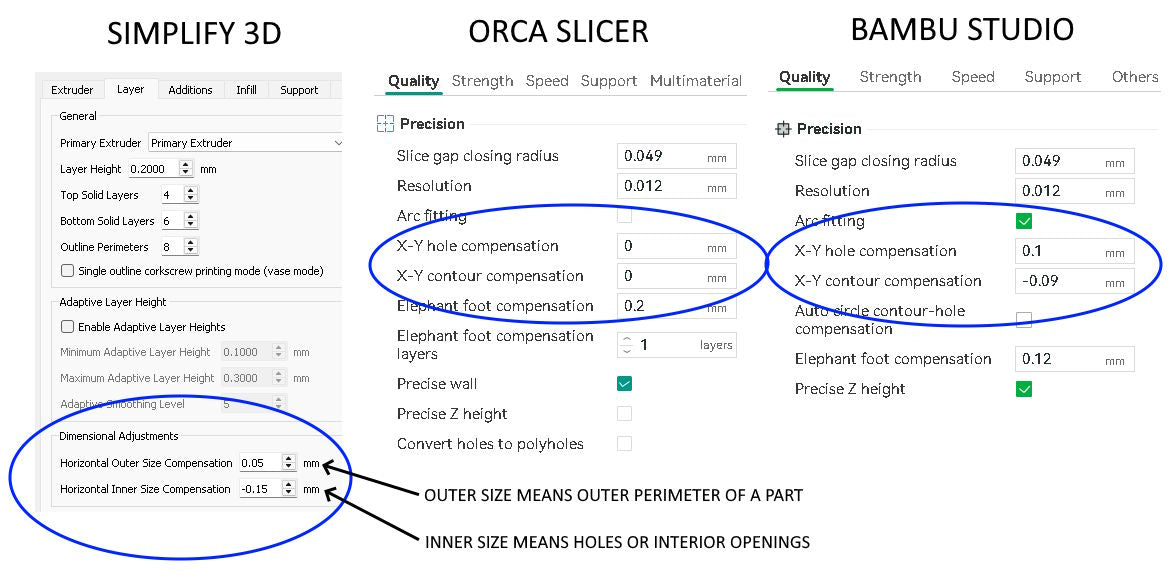
images of different slicer XY compensation settings
Shrinkage vs Compensation
Here is where things start to get complicated. Suppose you start with a new material that you've never printed before, and you want to work out some precision settings to print this material very accurately. You'll need to print test parts as you work on quality issues. And once your quality is dialed in, then you need to work on shrinkage and compensation adjustments to print sizes accurately. Suppose you print a standard 10mm x 10mm x 100mm shrink test part. You measure it and find the measured size is different from the modeled size. How do you determine which portion of those measured deviations are due to shrinkage, and which portion is due to compensation (offset) error? You are dealing with two deviations, and you must separate the two in order to adjust each one accurately. We have developed a spreadsheet to make this easier. It works based on the fact that once you enter the correct amount of shrinkage correction into your parameters, when you print a part the measured deviation will then be the same amount in both X and Y, because compensation ( or offset ) adds or subtracts an equal amount from all walls. So, the spreadsheet takes your starting modeled part size, compares it to your final cooled part measurements, and then applies a range of shrinkage values to these measurement, and lists each in a separate row. Then each row calculates the amount of measured deviation that is left in X and Y (after applying the shrinkage compensation). You simply find the row where the difference in X and the difference in Y are as close to zero as possible. That row will show you both your shrinkage rate, retention rate, and the amount of XY compensation you need for your outer perimeters. Whew! That was a thick paragraph. You can download the spreadsheet and look at the formulas if you want to understand the math behind it. It does eliminate a lot of trial and error printing. Download the shrink test STL files and excel shrink rate calculator here SHRINK RATE FILES
Other Shrink Factors
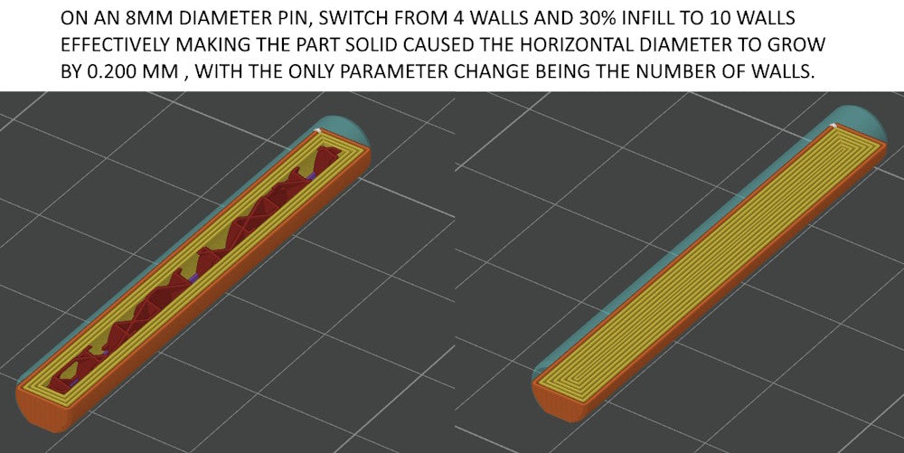
Other factors can affect the overall way a part shrinks and the scale factor. For example, we discovered on this 8mm diameter pin that switching from 4 walls and 30% infill to printing it solid by setting it to 10 walls caused the horizontal measured diameter of the pin to grow by 0.200mm. No other parameters were changed. This underscores the earlier point about finalizing your print quality, and all your parameter settings, before making the adjustments to correct for shrinkage and XY compensation.
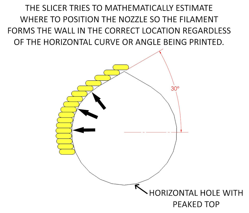
Non Vertical Walls
The slicer has to mathematically calculate where to position the nozzle relative to horizontal curves or angled walls so that the plastic is printed and the wall formed in the correct location. Many people would assume that if you have the shrinkage rate and xy compensation dialed in accurately, that the printer could print these angled features accurately. But they would be wrong in assuming that. Almost always, when you start attempting to print with high precision, you'll find that the vertical walls and height of the part can be near perfect, while the size of horizontal holes or angled surfaces is not true to modeled size. I've had to model horizontal holes sizes as much as 0.200mm larger or smaller from the desired size to get the printer to print them the correct size.
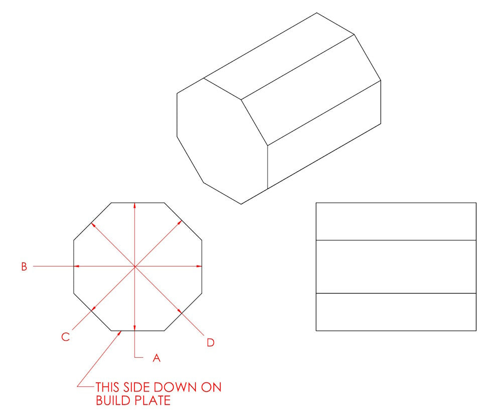
Try printing an octagonal shaped part like the one below, and you'll likely find that the A and B dimensions can be spot on while the C and D dimensions are off by 0.100mm or more. These errors have to be dealt with by changing the 3d model when precision really matters. There is no independent control for how angled surfaces are compensated in the slicer.
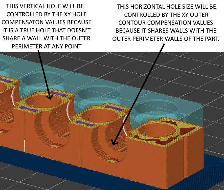
Inner vs. Outer Compensation
Not all holes in a 3d printed part are controlled by the X-Y hole compensation value in the slicer. In the case of a horizontal or vertical hole, if it shares an outer wall with the outer perimeter of the part, then the X-Y outer contour compensation will control the size of the hole. For the X-Y hole compensation value to take effect, the hole must have it's own wall around the inside of the hole that isn't a wall shared with any outer contour of the part. See the examples below. For this reason, to adjust the final printed size of horizontal holes or holes that break out into the outer boundary of the part, it's necessary to change the modeled size of the hole. If you change the X-Y outer contour compensation value in an attempt to change the hole size, this will also change the size of all of the outer perimeter of the part.