RC CONTROLS FOR BEGINNERS
Our hope in sharing this information is to provide a very concise overview of how RC controls work for those who are just starting out, and would rather not piece it all together by watching a hundred YouTube videos.
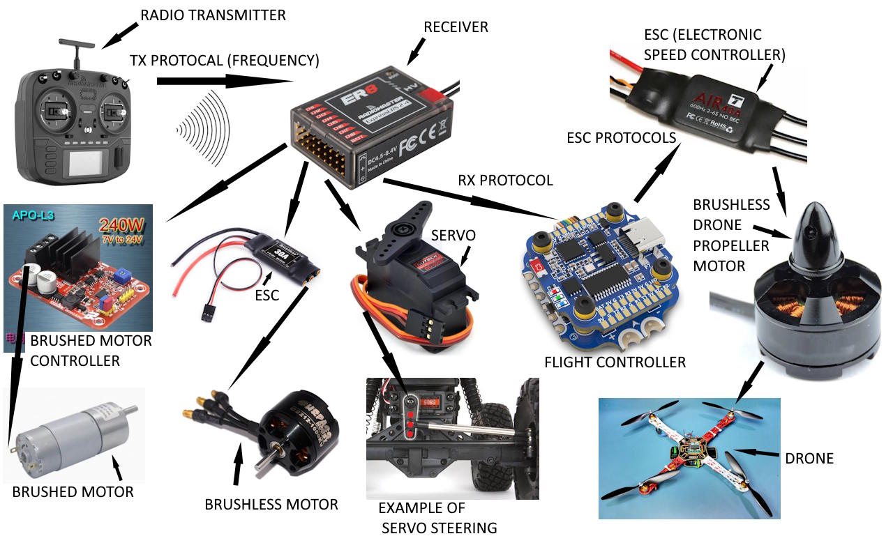
Basic Overview of RC Devices and What They Connect To
RC RADIOS
An RC radio, otherwise known as a transmitter, is the hand held device where the user manipulates joy sticks ( gimbals) and switches to control the RC toy. Two of the more popular brands today are Radiomaster and FRSky. The radio communicates wirelessly with an RC receiver. The receiver is installed on the RC toy and translates the signals from the radio into output commands to control motors and servos. Most radios have two Gimbals with forward and back motion as well as left and right motion. Each of these motions represents a different input control, or channel. With most programmable radios you can configure in the firmware (software) which channel is mapped to which input. For example, the forward and backward motion of the right gimbal could be mapped to control channel 1 on the receiver. The communication between the radio and the receiver is called a Tx protocol (the T stands for transmitter), which refers to the language, or frequency that these device communicate on. Examples of TX protocols are ExpressLRS and TBS Crossfire. You must use a radio and receiver that have the same protocol in order for them to link and communicate.
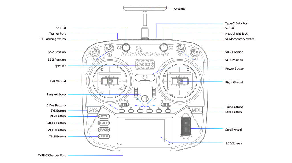
Radiomaster Boxer Radio Layout
RC radios are highly configurable. You can control a tremendous range of things through the firmware, such as causing the gimbals to control different channels by flipping a toggle switch on the radio. Switches on the radio can be mapped to other channels to control things that are not proportional, meaning they are only on or off controls, like turning on or off lights, or raising and lowering landing gear.
RC Receivers
The RC receiver is the part that communicates wirelessly with the radio, and receives the wireless commands, and then sends out those commands through the various channels to control motors and servos. Receivers for RC land devices are usually a little different from those for flight devices. The receiver will have antenna wires for picking up the signals from the radio. The receiver will also have a place for receiving power from a voltage supply device like an BEC (battery elimination circuit). More about connections later. The receiver will also have pin connections that are for each of the channels. A receiver normally has a fixed number of output channels, like 4 or 8 for example. The communication between the receiver and the devices it will control is called an Rx protocol (the R stands for Receiver). Unlike Tx protocols, Rx protocols are wired, meaning physical wires connect the receiver to the devices it will control.
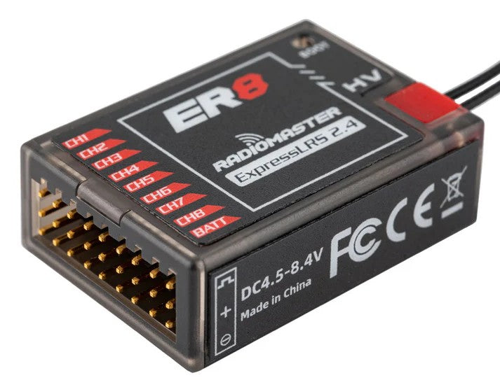
Radiomaster ER8 Receiver
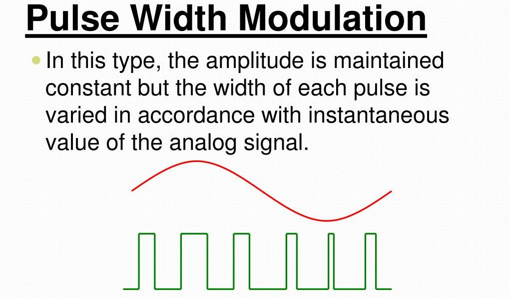
Pulse Width Modulation
Receivers communicate with downstream devices using an Rx protocol. There are many of these protocols to choose from, but one of the most common is PWM, or pulse width modulation. Do not confuse this with pulse frequency. The receiver sends a pulse every so many milliseconds ( ms ) which is the frequency. It's the width of that pulse that determines the command the receiver is giving (See image below). With RC, the width of the signal pulse normally varies between 1000µs and 2000µs (micro seconds). So this range will determine the behavior of down stream devices. Motors and servos normally have a neutral position which is 1500µs pulse width for a stopped motor and for a non-continuous servo 1500µs would be center position. The minimum pulse of 1000µs width will cause motors to turn max speed in one direction, and the maximum pulse width of 2000µs will push them to maximum RPM in the other direction, normally. Although the behavior of all this can be highly configured by the radio. For example the throttle control on a plane propeller never needs to turn in reverse. So the radio can be set so one of the gimbals is at rest in the full back position and it applies power to the propeller motor all in one direction as the user pushes the gimbal through its full range of motion from back to forward.
RC Servos
An RC servo is basically a dc motor, but one that has the ability to control its position of rotation and stop at almost any position within its range of motion. Servos come in both analogue and digital, and they also come as either positional or continuous. A continuous servo will rotate like any other motor, but with more control over speed and the position it can stop at. A positional servo has a specific range of rotation such as 90, 180, or 360 degrees. Positional rotation servos will cycle to any position within their range of rotation, based on the input from the radio, or specifically the width of the pulses it is receiving from the receiver. Servos are connected to and control the flight surfaces such as ailerons, elevators, and rudders on RC planes. They also control steering on RC land based devices such as cars and crawlers.
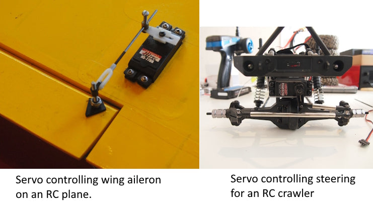
RC Servos Connected to Ailerons and Steering Linkage
Continuous rotation servos basically behave the same way as motors, described above. With positional servos, there is normally a neutral position configured for the servo, which would be the position it would return to if you take your hands off the gimbals or steering wheel. For example in an RC car, neutral would be set up such that at neutral position the front wheels of an RC car would track straight. Neutral would be represented by 1500µs pulse width. Moving the steering control on a radio to the maximum in one direction would output a pulse width of 1000µs and cause full servo actuation in one direction, and thus full steering turn in one direction. Moving the same radio control to the maximum opposite position would output 2000µs pulse width and cause the same maximum steering, but in the opposite direction. The output between neutral and full is proportional. So a steering control position 25% of the way from neutral to full would send pulse widths that move the servo 25% of it's rotation in one direction from neutral to full, and 50% on the steering control would do the same at 50% servo position and thus 50% of steering angle. This description is a bit over simplified but it's the most common scenario and conveys the concept correctly. All of this is highly configurable via the radio. You can set neutral to any position and adjust the range of motion through the firmware of your programmable radio.
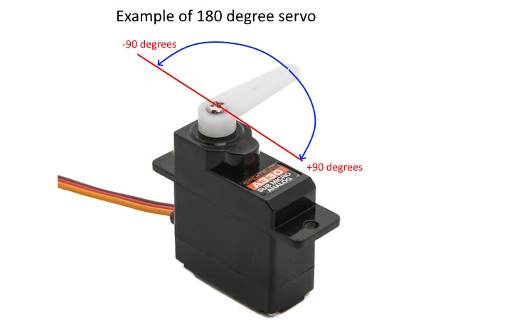
Image Illustrating the Range of Motion of a 180 Degree RC Servo
Electronic Speed Controllers (ESC)
An electronic speed controller is commonly called an ESC, and there are different kinds, namely brushed and brushless. A brushed ESC is for a brushed DC motor. I will spare you the explaination of brushed motors vs. brushless motors, you can google that. The connection between the esc and a brushed motor is 2 wires, + dc voltage and - or neutral. Thus a brushed motor only has 2 wires or connection points. The direction of rotation, clockwise vs counter clockwise, involves switching the + and the - voltage being sent to the two wires or connection points on the motor. Speed is determined by voltage from zero to the maximum allowed voltage for the given motor. And the speed controller ( ESC ) calculates what voltage to send to the motor based on the pulse width modulation, or width of the pulses being sent from the radio to the receiver. Brushless DC motors are more like a 3 phase motor, and use 3 wires to connect to the ESC. The brushless ESC controls both speed and direction of the motor by how it sends the voltage signals to the 3 connecting wires.
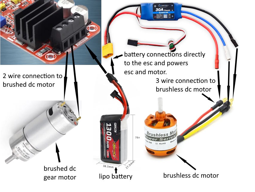
ESC Connections to Brushed and Brushless Motors
Flight Controllers
A flight controller sits between (electrically speaking) the RC receiver and the servos, esc's, or motors that are used in a flighing RC device. A flight controller is basically a small computer, and is the central component of a drone or UAV (unmanned aerial vehicle) that manages and stabilizes flight by interpreting onboard sensor data and commands coming from the RC receiver, and sending out commands to motors and other onboard systems. Flight controllers come in various types made for drones and fixed wing aircraft, including basic models with core stabilization functions and all-in-one versions with built-in features like GPS, barometers, and electronic speed controllers (ESCs). These all-in-one flight controllers simplify drone builds by integrating multiple functions into a single board. In contrast, modular flight controllers offer greater flexibility and customization, allowing users to attach external ESCs, GPS units, telemetry systems, and other components. Whether you're building a racing drone, a camera drone, or a fixed wing RC plane, selecting the right type of flight controller is essential for performance, reliability, and ease of setup.
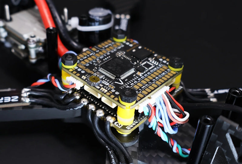
image of a flight controller installed in the center of a drone
LiPO Batteries
LiPO batteries are popular for RC because they do a great job maintaining voltage over their discharge curve. A LiPO battery is a multi cell battery. Each cell contributes to the overall voltage of the pack. Below are some values worth knowing.
Peak Voltage 4.2 volts per cell, never charge above this. Minimum Voltage 3.0 volts per cell, going below this is risking damage. Safe Voltage is 3.3v per cell. Stop your RC device before the batteries are drained below safe voltage. Practical voltage is about 3.5v, and it's best if you don't run them below this. You will start to feel the power loss at this level. Voltage decreases under load and will rise again a little after the load is removed. Storage voltage 3.75 to 3.85 volts per cell is perfectly ok. Nominal Voltage is 3.7 per cell. This value is used for determining pack voltage.
Below are the nominal and peak voltages for 3, 4, 5, and 6 cell LiPO batteries.
3s 11.1/12.6
4s 14.8/16.8
5s 18.5/21.0
6. 22.2/25.2
Studies show that lowering your full charge voltage from 4.2 to 4.15 increased battery live cycles by 50 tp 100 percent. If you drop your full charge voltage to 4.1 you will increase the life by 100 to 200 percent.
Markings on the batteries:
450 mAh battery is 450 milliamp hours of stored energy, equates to how much work it can do. Discharge rate is normally listed as two numbers such as 30-40C. These values are continuous/burst values. So 450 mAh converted to amps is .450 amps. You take the amps times the discharge rate to find out what amperage the battery can deliver continuously and also can deliver in a burst for a short time. The battery pictured below only has one discharge rate listed, so .45 amps times 30, it can deliver 13.5 amps continuously. These values found on the batteries are often highly inflated. Only use balance charger for LiPO batteries. Some trickle chargers will charge through the balance wires but most charge using the main power wires to charge and they monitor/balance the voltage of each cell using the smaller balance wires. (balance wires are the white connectors below)
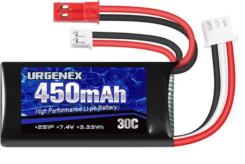
Image of a 7.4 volt LiPO battery
RC Connectors
Several different kinds of electrical connectors are used in the RC world. We will examine each in some detail below. The first image below gives some terminalogy about the different parts that make up an electrical connector.
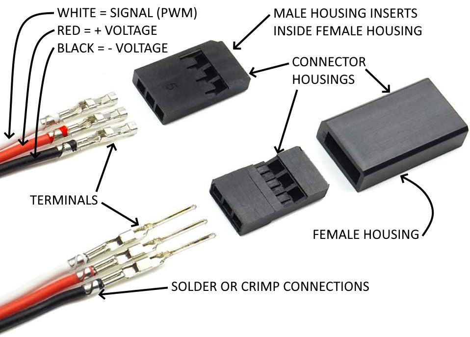
Diagram of the DIfferent Parts of an Electrical Connector
Futaba / JR Connector
The Futaba/JR connector is a 3 wire plug that connects to the receiver and carries the signal to down stream devices like servos and electronic speed controllers. See image below. These connectors have a signal wire (PWM), and + voltage wire, and a ground or neutral wire. The wire color pattern isn't always the same. Refer to the image for servos below for an example of wire color patterns. Most of the time the male end has pins or plugs and the female end has receivers or sockets. However, on the Futaba/JR connector, the male and female labels refer to the housing, not the terminals. And the male housing has sockets inside of it while the female housing has the pins. I know, it's wonky. Don't think about it too much......
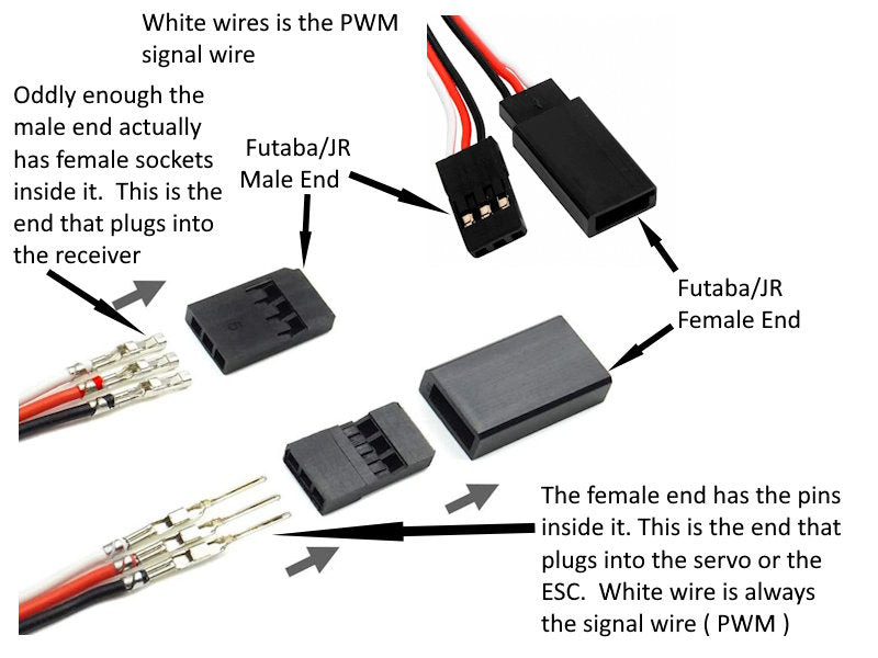
Futaba/JR Connector Diagram
Bullet / Banana Connector
The Bullet connector (called Banana connector if you are from banana country) is an easy and fast way to make high current connections such as when charging batteries or running motors. Many battery chargers use this type of connection. You can buy premade cables or just the ends and solder them onto your own wires. There are many sizes of these available. As the positive and negative wires both use the same connector, take care to get this right using the wire colors. If you plug these in reversed you can fry sensitive electronics. 2mm-8mm is the range of sizes used in RC cars, with 4mm and 5mm being the most common. There are many different brands and styles of banana plugs, and the amperage rating and recommended wire size varies greatly across the industry. Because of this we will not quote any specs here. It is best to get the specs for amp rating and wire size for the exact banana plug you buy. Step carefully here. In the RC world, you will find statements online for banana plugs that will say something like "rated for 40 amps, 14 AWG wire". This is absurd, because on every electrical chart a 14 AWG is only rated for 15 amps. What these statements mean is the plug can handle 40 amps and accept a 14 AWG wire. This does NOT mean a 14 AWG wire can handle 40 amps. The limiting factor is the wire size. If you push too many amps through too small of a wire, it will overheat and can catch on fire. Proceed with caution.
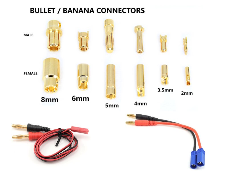
Examples of Bullet / Banana Connectors
Deans / T-Plug Connector
Deans or T-Plug connector is commonly used with modern LiPO (Lithium Polymere) batteries and it has been an industry standard in the past. There are other battery connectors that are more popular now, but being simple and most importantly cheap it is still a very popular RC-lipo connector today. This plug has the advantage of only allowing a connection one way, due to the orientation of the spring plugs. Provided the wires are always connected correctly, it's impossible to accidently reverse polarity with this plug.
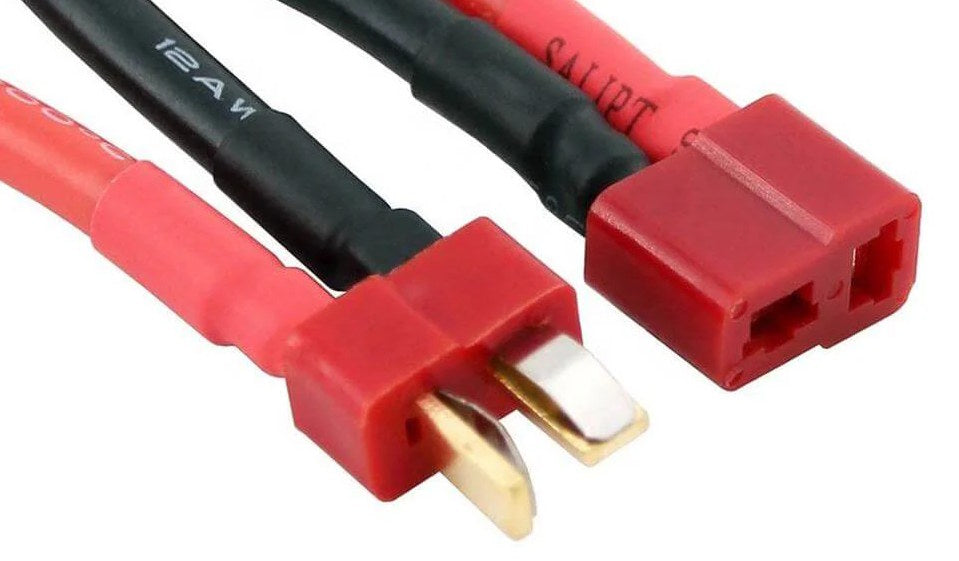
Dean's or T Plug Connector
XT Connectors
XT connectors have come along as a replacement for the older T plugs in making LIPO battery connections for RC applications. It's basically a bullet connector with a high temperature nylon housing that only allows the user to connect in one orientation, thereby eliminating the chance for a reverse polarity connection. There are 3 different sizes of XT connectors, but XT-60 is the most common for battery connections today. The Larger XT-90 is used for very high current applications such as 1:8 scale RC crawlers or cars. As with bullet / banana connectors, the connector itself is usually rated for much higher current than the wire size that can be soldered to it. Be careful to use a sufficient wire size for the amps that you need it to carry.
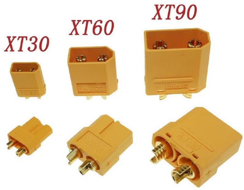
Different sizes of XT connectors
JST-RCY or BEC Connector
The JST-RCY or otherwise known as the BEC Connector is a 2 pin red connector used for RC auxillary equipment, external BEC (Battery Elimination Circuits), and for radio transmitter or receiver battery.
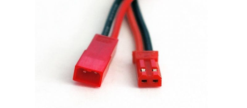
The JST-RCY or BEC Connector
JST-XH, Balancer Cable Connector
There are many connectors that use the name JST, but in the RC world we usually use just the JST XH and JST RCY-family. This connector is commonly found on LiPO batteries and plugs into the balancing port on a charger, functioning as a charge balancer cable. The number of pins roughly corresponds to the number of cells in your LiPO battery, as each cell is monitored by the charger to balance the charger rate across all cells.
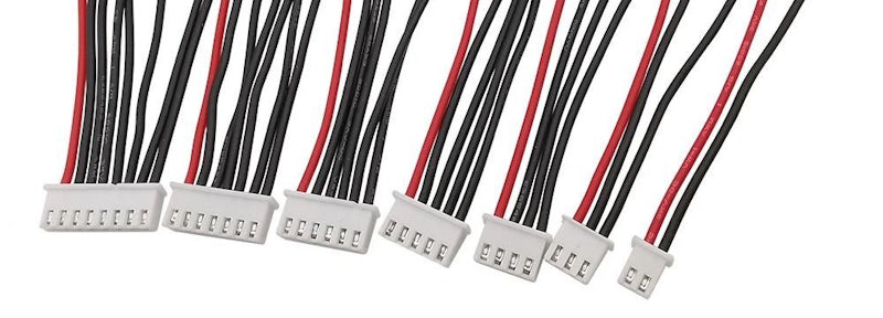
Image showing different sizes of JST-XH balancer cable connectors
Other RC Power Connectors
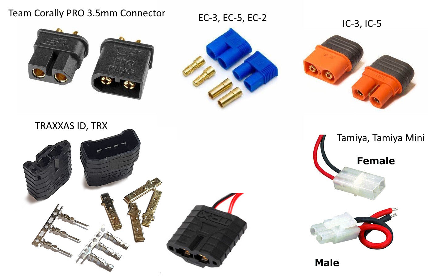
The other RC battery and motor connectors are all less common and are shown below. All of these are for power transmission. The Team Corally PRO 3.5mm connector has some features of the plastic housing that further help prevent reverse polarity, and is a great replacement for the XT-60 connector. EC-connectors use standard sized Bullet terminals and have a heat resistant nylon housing. Because the terminals are separate from the housing, soldering these can be a bit easier than the XT connectors. IC-3 and IC-5 are developed and patented by Spektrum Smart Technologies. IC-connectors are backwards compatible with EC connectors, meaning you can use batteries with EC connectors on a device with IC connectors. Batteries with IC-connectors require a Spektrum Smart -battery chargers. The Traxxas ID is specific to the the Traxxas brand of RC toys and are only found on their brand of toys and chargers. The Tamiya connector is the dinosaur of all RC Battery connectors, the granddaddy of them all. It's slim, simple, easy to assemble, has a plastic retainer clip, and cannot be connected in reverse polarity. The important thing is that you match up connector types for compatibility when buying various RC components or be ready to solder new connectors onto your wires to maintain consistency across components in your RC system.
RC Wiring Connections
In order to build and RC system you will need to understand how it all connects and how the signals and power are delivered to the various components. Below we will detail how the various parts of an RC system are connected, how power is supplied to each component, and how the system communicates. We will keep this in the simplest possible form. Much more detail is available in YouTube videos that go into great detail about each component or type of RC system. And there are endless variations on how a system can be configured and how it can communicate.
Servo to Receiver Connection
Perhaps the simplest of all connections is the servo to receiver using the standard Futaba / JR Connector. Servos come with this connector already installed normally, and you simply plug it in to the channel of your choice on your receiver. The servo gets its power to operate from the receiver. Make sure you get it oriented so the signal wire is connected to the correct pin on the given channel.
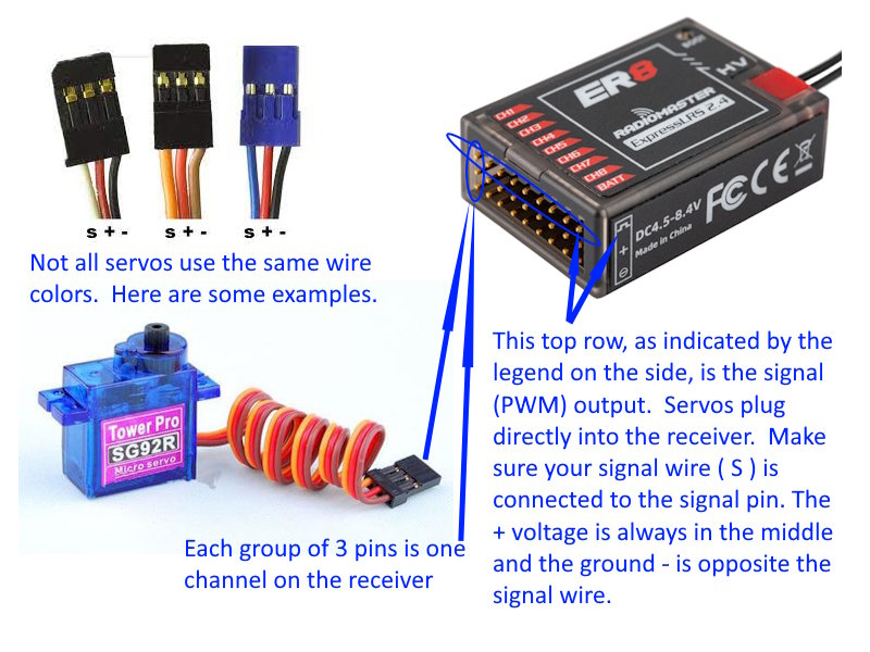
image showing the arrangement of pins on a receiver and how a servo connects
ESC to Receiver Connection
An ESC, or electronic speed controller, is used between the receiver and a motor. Its job is to interpret the signal coming from the receiver and output the correct voltage and direction signal to the motor to control the speed and direction the motor turns. A battery is connected directly to an ESC to power it and the motor it is controlling. Wires coming from the ESC will be either 2 wires for a brushed motor or 3 wires for a brushless motor. The Futaba / JR connector is plugged into one of the channels of the receiver. In the case of an airplane or a RC car, the motor driving the propeller or wheels would be connected to the throttle channel on the receiver.
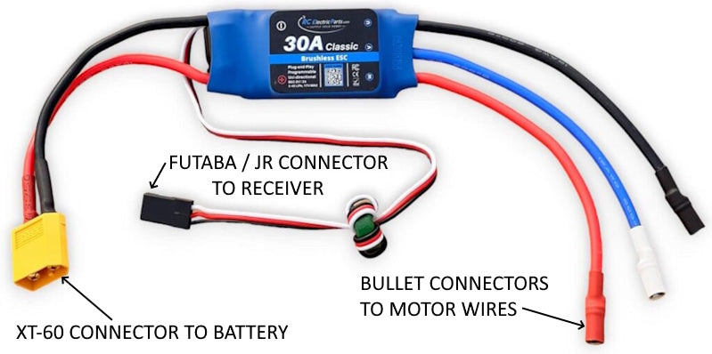
IMAGE OF ESC (ELECTRONIC SPEED CONTROLLER) WITH WIRES LABELED
Battery to Receiver Connection
You may remember that previously we said that a battery connects directly to an electronic speed controller ( ESC ) and supplies power to the ESC and the motor it is controlling. The RC receiver itself has to get power to operate from somewhere. There are basically 3 ways to connect power to a RC receiver. FIrst, you can connect a dedicated battery directly to the power port ( BATT ) point on the receiver to supply the needed DC volts your receiver requires. Please note, this method is not common, and your battery MUST output the right voltage for your RC receiver. Second, if your ESC has an onboard battery elimination circuit ( BEC ) as most do, then when you connect the ESC to a RC receiver channel using the Futaba / JR connector, it will supply power to the RC receiver via the wire that is the +V (positive) voltage. This is normally a red wire, and situated in the middle of the Futaba / JR connector between the signal wire (PWM) and the -V or ground wire. NOTE: the ESC is receiving the command signal (PWM) from the receiver via the signal wire on whatever channel it is plugged in to, while at the same time supplying power back to the receiver through the +V wire on that same channel so the receiver can power on and operate. All the +V pins on a receiver are connected together internally, and all the -V pins on a receiver are connected together. So if you supply power to the receiver through any one +V pin on a single channel, it supplies power to the entire receiver, which power then is distributed and used to operate the servos that are connected to the receiver. The third way to get power to the RC receiver is to connect it to a dedicated battery elimination circuit ( BEC ) device that is then connected directly to whatever battery is powering your RC device. A battery elimination circuit ( BEC ) is an electronic voltage regulator used to step down voltage from whatever voltage source is powering your RC motors to the DC volts needed to power your RC receiver. IMPORTANT! A receiver can only receive voltage from a single source, NOT more than one source. If using a dedicated BEC device or a battery to power your receiver directly, you must disconnect the red wire from all ESC devices so as NOT to supply voltage to the receiver from multiple sources. If you get this wrong, you will likely burn up some electronics.
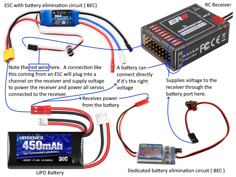
image showing the ways power can be supplied to an RC receiver